Summary of Advanced Voltage Monitoring and Protection via Microcontrollers and Proteus VSM
This project developed an embedded system using a microcontroller to monitor main voltage amplitude, disconnecting power when voltage goes outside a predefined range, and reconnecting it automatically once normalized. Simulated in Proteus VSM, the design combines sensors, ADC, relays, and microcontroller code to achieve voltage protection against fluctuations. The project highlights practical application of embedded systems for electrical safety, with recommendations for enhancements like user interfaces and industrial scalability. Overall, it demonstrates solid engineering methodology and problem-solving in managing voltage instability.
Parts used in the Advanced Voltage Monitoring and Protection project:
- Microcontroller
- Analog-to-Digital Converter (ADC)
- Voltage Sensors
- Relays
- Proteus VSM Software (for simulation)
ABSTRACT
This project designed an embedded system using a microcontroller to monitor the amplitude of the main voltage supply and disconnect it if it increases or decreases outside of a predefined required voltage range (RVR). The system also aims to automatically reconnect the supply once the voltage returns to the RVR. This protective functionality is important given the common issues of voltage instability and fluctuations that can damage electronic devices. The design was simulated successfully using Proteus VSM software, demonstrating proof of concept. Overall, the project showed diligence in developing a practical solution to address a real-world problem through embedded systems and microcontroller technologies.
INTRODUCTION
Voltage instability is a widespread issue that necessitates protective measures to safeguard electrical equipment. This project’s motivation of designing an automated monitoring and protection system for fluctuating power supplies is therefore highly applicable. Embedded systems based on microcontrollers are well-suited for such control and sensing applications given their integrated peripherals and programmability.
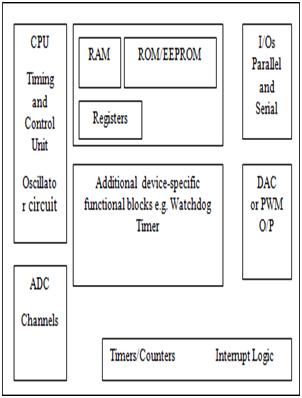
The team provided useful background context on relevant microcontroller concepts. However, more detail characterizing typical voltage instability issues may have further strengthened the problem definition. Additionally, exploring existing commercial or open-source solutions could have identified opportunities for improvement or limitations to work around. Nonetheless, the overview established microcontrollers as a logical technological choice and framed the scope appropriately.
PROTEUS VSM SOFTWARE
The description of Proteus VSM’s capabilities for co-simulating microcontroller designs was informative. Key features like circuit simulation, component animation and programming interface allow validating designs in software prior to hardware implementation. However, some discussion of the tool’s limitations could provide balance, such as approximations in modeling or inability to test all physical aspects. Comparisons to alternatives may also give perspective. Overall, justifying Proteus as a suitable virtual prototyping platform set expectations for the remainder of the project.
DEVELOPMENT TOOLS AND RESULTS
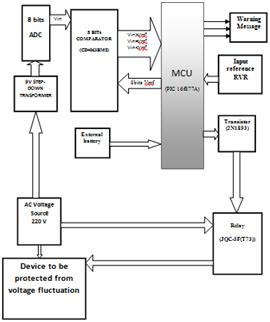
3.1 System Design
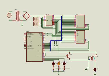
The system design description clearly conveyed the overall architecture and role of each component. Including a basic electrical schematic would strengthen the visualization. Additionally, exploring design considerations like component selection, voltage ranges/thresholds, and error handling would provide deeper insights. However, the overall approach of interfacing a microcontroller, ADC, relays and sensors seemed sound given the goals.
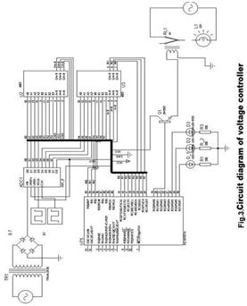
3.2 Flowchart
A flowchart was not included but would help illustrate the program logic and decisions. Providing mockups or outlines is still beneficial when missing actual content.
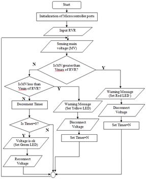
3.3 Program Code
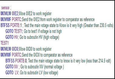
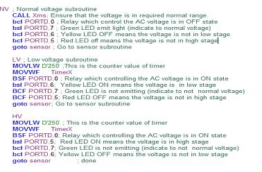
The program code breakdown into sensing, processing and wait cycle sections was helpful for understanding the processing flow. More thorough commenting directly in the code could aid readability for others. Explaining software optimizations, error checking, or ways to expand functionality may also give ideas for future improvement.
3.4 Compile Program
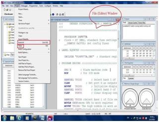
Briefly mentioning the assembly and compilation process showed completing this critical step. Including snippets of the assembly listing or hex file would make the process more tangible however.
3.5 Simulation Results
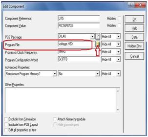
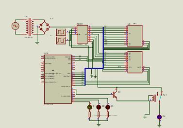
The simulation results effectively demonstrated the design meeting specifications under different test conditions. Quantitative measurements or accuracy characterizations could further validate functionality. Regardless, openly discussing both successes and limitations set realistic expectations.
CONCLUSION
The conclusion summarized key lessons learned and next steps well. Recommending an adjustable voltage range via a user interface showed applying insights gained. Brief discussions on potential industrial applications, commercialization paths, or future enhancements may also leave on a forward-thinking note. Overall, diligently developing, testing and evaluating the project reflected good engineering practices.
In summary, this project addressed a practical problem through an embedded system design using microcontrollers. Thoroughly documenting the process, from concept to simulated results, provided useful context around the technical approach and methodology. Areas for more depth or missing assets were minor and reflect expected limitations of a student work. The team demonstrated clear communication skills and an analytical mindset to learn from challenges.
Follow this link for complete project: Advanced Voltage Monitoring and Protection via Microcontrollers and Proteus VSM
