Summary of The Minute Timer Based on the PIC16F88 MCU
This article details a beginner's minute timer project centered on the PIC16F887 microcontroller. It features a 7-segment display, six buttons for input, and a 9V battery power source. The device allows setting timers between 1 to 99 minutes using specific button combinations and includes a visual LED indicator for two-digit modes. An alarm sounds when time expires, and the system can be reset via a dedicated button.
Parts used in the Minute Timer:
- PIC16F887 microcontroller
- 7-segment display
- 6 buttons
- 1K resistor (6 pieces)
- 470 resistor (9 pieces)
- 7805 voltage regulator
- 0.33 uF capacitor
- 0.1 uF capacitor
- Piezo speaker
- Battery holder
- Switch
Let’s take a look at the simple beginner’s project of the minute timer. The heart of the project is the 8-bit PIC16F88 MCU. The time is shown on the 7-segment display and the timer is operated using 6 buttons. The device is powered by the 9 volt battery.
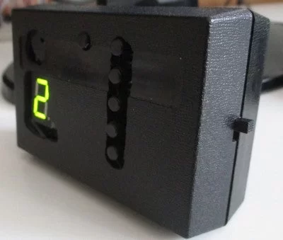
The time range is from 1 to 99 minutes. The two digits number mode is indicated by the additional green LED that is located on the right side of the display just next to the decimal point sign. The five buttons in a row represent numbers one to five. The sixth button has two functions – to reset the device and to change the current digit that is being entered.
The timer device works the following way. After the main switch is on, a zero digit is displayed and the device is waiting for the buttons to be pressed. There are 3 possibilities:
1) To enter 1 to 5 minutes period just press one of the five buttons. The countdown starts in a few moments.
2) To enter 6 to 9 minutes period press any of the five buttons and right after that repeatedly press the 6th button to achieve the desired value. After each press the value is incremented by 1.
3) To enter 10 to 99 minutes period enter the first digit using the instructions in the previous step. Then press any of the five buttons. The decimal point and the additional green LED turns on indicating that the second digit of the value is being entered. Now press the 6th button repeatedly to adjust the second digit value.
While the countdown is in progress the remaining time is being displayed and the decimal point is periodically blinking. In the case of the two digit number both digits periodicaly appear on the display with the second digit being marked by the decimal point. As long as the remaining count of minutes is a two digit number the additional LED is on.
When the remaining time reaches zero value the sound alarm will be triggered. The device then can be reset by the 6th button to be ready for the next task.
Step 1: Parts Needed
- PIC16F88
- 7- segment display
- 6 buttons
- 1K resistor – 6 pieces
- 470 resistor – 9 pieces
- 7805 voltage regulator
- 0.33 uF capacitor
- 0.1 uF capacitor
- a piezo speaker
- a battery holder
- a switch
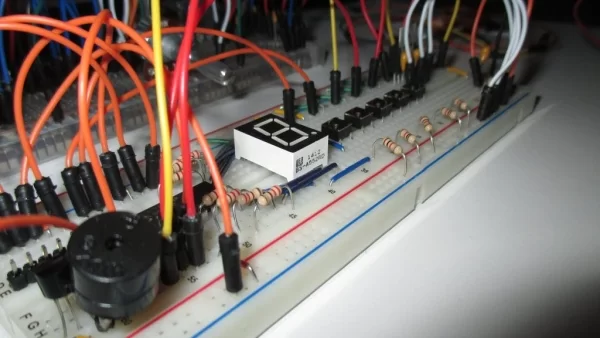
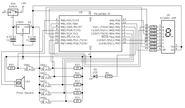
Step 2: The Circuit of the Timer
Step 3: The Source Code
The code written in C using MPLAB X IDE and XC8 compiler is available for download:
Attachments
Step 4: The Final Device’s Look
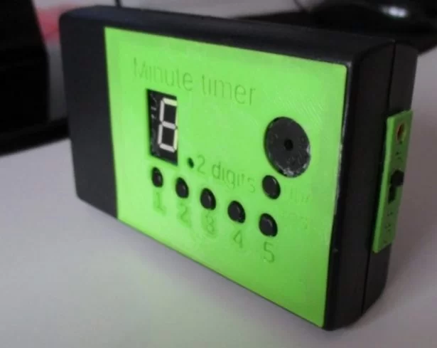
It is up to you whether you only assemble the circuit on the breadboard or create some unique design. I enclose some images of my devices.
Source: The Minute Timer Based on the PIC16F88 MCU
- What is the heart of this minute timer project?
The heart of the project is the 8-bit PIC16F88 MCU. - How many buttons are used to operate the timer?
The timer is operated using 6 buttons. - What is the maximum time range for the timer?
The time range is from 1 to 99 minutes. - Does the device indicate two-digit numbers visually?
Yes, an additional green LED indicates the two-digit number mode. - How do you enter a value between 10 and 99 minutes?
Enter the first digit, press any of the five buttons, then use the sixth button repeatedly to adjust the second digit. - What happens when the remaining time reaches zero?
A sound alarm will be triggered. - Can the device be reset after the alarm sounds?
Yes, the device can be reset by the 6th button to be ready for the next task. - What programming language was used for the source code?
The code was written in C using MPLAB X IDE and XC8 compiler.