
Summary of 8 Channel PWM LED Chaser for PIC16F628A and PIC16F88
This project is an 8-channel LED chaser using a PIC16F628A microcontroller providing 5-bit PWM for four intensity levels per LED, multiple chase sequences and modes, and non-volatile storage of the selected mode. It includes an ICSP header for in-circuit programming and runs from a 9–14V DC input with onboard 5V regulation. The design is simple, suitable for learning PIC assembly, and can be built on PCB, stripboard, or breadboard.
Parts used in the 8 Channel PWM LED Chaser for PIC16F628A:
- PIC16F628A microcontroller (IC2)
- 7805 5V regulator (IC1)
- LED1 to LED8
- Resistors R1 to R8 (current limiting for LEDs)
- Resistor R9 (pull-up for switch S1)
- Resistor R10 (pull-up for MCLR)
- Resistor values for LK1/links as required
- Capacitor C1 (decoupling for PIC Vdd)
- Capacitors C2 and C3 (stabilize voltage regulator)
- Diode D1 (reverse polarity protection)
- Switch S1 (mode control)
- J1 power input connector
- JP1 ICSP header (for in-circuit programming)
- PCB or stripboard or solderless breadboard
Description
This neat little circuit provides 8 LEDs directly driven from the PIC along with a single mode control switch. The firmware elsewhere on this page drives the LEDs with a 5 bit PWM signal providing each of the 8 LED channels with four levels of intensity; off, dim, mid, bright. A number of sequences are programmed into the firmware to provide some interesting visual effects and chase sequences, including the classic effect seen on the car in the Knight Rider TV series.
The software has sequential, random and manual sequence run modes and manual advance to the next sequence in any mode. The selected sequence and mode are also saved to non-volatile memory so it will always restart in the selected mode.
The design is deliberately simple with each LED being directly driven from a PIC I/O pin. This and the inclusion of an in-circuit programming header (ICSP) make the circuit ideal for teaching/learning introductory PIC assembly language programming.
You can use it with different sized LEDs and mixed colours, as well as fewer than 8 LEDs. As well as using it as a LED chaser it is great for adding effects to toys and models. See FAQ
However, if you just want a cool LED chaser without having to write any code, a ready written LED chaser program including 34 chase effects with source code and programmer ready HEX files is provided at the bottom of this page.
The circuit has been constructed on a PCB but can easily be built on strip-board or a solderless breadboard.
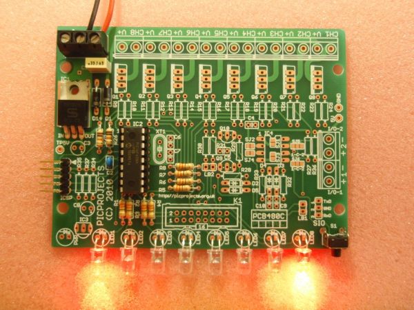
Circuit Description
The heart of the LED chaser is the PIC 16F628A microcontroller, IC2. The program that runs on this chip controls the LEDs attached to the output port pins. Resistors R1 thru R8 limit the current through LED1 – LED8 to a safe level that won’t damage the PICs I/O ports or LEDs. Resistor R9 provides a pull-up for the input connected to switch S1. R10 pulls up the PIC’s MCLR reset signal during normal operation while allowing the input to be raised to 12.5 volts during in-circuit programming. JP1 provides connection for an ICSP programmer such as a PICkit2 making it easy to reprogram the PIC without removing it from the PCB.
Capacitor C1 is used to decouple the 5 volt power supply to the PIC. If you’re building the circuit on a breadboard or stripboard you should ensure it is located close to the PICs Vdd connection (pin 14 ).
Power is supplied to the circuit via J1 and must be smooth DC between 9 and 14 volts. The PIC requires a precisely controlled 5 volt supply and this is provided by IC1, a 7805 3-terminal, 5 volt regulator. Typical current drawn by the circuit with all LEDs on is only around 100mA so the voltage regulator doesn’t require any additional heatsink. Capacitors C2 and C3 stabilize the regulator. Diode D1 protects the circuit from accidental reverse polarity of the input voltage.
Notes:
- Capacitors C2/C3 stabilize the voltage regulator and may be omitted for most applications, however the schematic shows them and the PCB layout makes provision for them. If you’re unsure whether you will need them then it’s best to install them.
- The latest high brightness LEDs are very bright even with 270R current limiting resistors. However, if you do need to change these resistors for some reason take into account the maximum current that the PIC can source from an I/O port pin is 25mA, and also be aware that the output voltage will drop as you increase the load.
- If you install LEDs that require a lower value series resistor you may find you are unable to program the PIC in-circuit via the ICSP header. This is because the I/O port pins on the PIC that are used for In-Circuit Serial Programming are shared with the LEDs. The programmer may be unable to drive these lines when lower value resistor are used. With the 270R resistors and PICKit2 programmer, In-Circuit programming should work without problems.
- JP1 is an ICSP header to allow programming of the PIC while installed in the circuit. It is only required if you intend to connect a programmer to modify the sequences or code. It is not supplied with the kit.Pin 2 of this header connects to the circuit’s 5 volt supply via the link LK1. Since the circuit provides an onboard 5 volt regulator, the circuit should be powered from this and the link left open. Pin 1 of the ICSP header JP1 is nearest the LEDs
- If you have an external 5V supply, you can omit D1, C2, C3 and IC1. You will need to install wire links in place of D1, and between pins 1 and 3 (in-out) of IC1. The circuit will now work from the external 5V supply. Be sure to connect it up correctly because without D1 in place there is no reverse polarity protection.
For more detail: 8 Channel PWM LED Chaser for PIC16F628A and PIC16F88
- What microcontroller does the project use?
The project uses a PIC16F628A microcontroller (IC2). - How many LEDs does the circuit drive?
The circuit directly drives eight LEDs (LED1 to LED8). - What power input voltage is required?
Power must be smooth DC between 9 and 14 volts supplied to J1. - How is the PIC powered with a stable 5V?
A 7805 3-terminal 5 volt regulator (IC1) provides the PIC with a regulated 5V supply. - Can the PIC be programmed in-circuit?
Yes, JP1 is an ICSP header allowing in-circuit programming with a programmer like PICkit2. - What does R1 to R8 do?
Resistors R1 through R8 limit current through LED1 to LED8 to protect the PIC I/O ports and LEDs. - Are C2 and C3 required?
C2 and C3 stabilize the regulator and may be omitted for most applications, but the schematic and PCB provide for them and installing them is recommended if unsure. - What happens if I use an external 5V supply?
You can omit D1, C2, C3 and IC1 and install wire links in place of D1 and between pins 1 and 3 of IC1, then power the circuit from the external 5V supply. - Will high brightness LEDs cause issues?
High brightness LEDs can be very bright with the shown 270R resistors; if lower value resistors are used programming in-circuit may be affected because ICSP lines are shared with LEDs. - Is the project suitable for beginners?
Yes, the simple design and ICSP header make it ideal for teaching and learning introductory PIC assembly programming.
