Summary of Automated Room Temperature Monitoring System using Microcontrollers
This paper describes a microcontroller-based server room temperature monitoring system using an Atmel ATmega8535 and LM35 sensor, with LCD and buzzer for local alerts, a Wavecom GSM modem for SMS notifications and remote control, and a relay board to switch equipment. The system alerts the administrator via SMS when temperature exceeds 28°C, accepts commands from a registered phone number to query status or control PORTC outputs, and was validated in real server-room tests meeting design specifications.
Parts used in the Room Temperature Monitoring System:
- Atmel ATmega8535 microcontroller
- LM35 temperature sensor
- Wavecom GSM modem
- MAX232 level shifter
- Liquid Crystal Display (LCD)
- Buzzer
- Relay board
- DB-9 connector (for modem connection)
- Transfer board
- Microcontroller board
Abstract
Monitoring the temperature within a computer server room stands as a crucial responsibility to uphold the server’s performance amidst potential disruptions caused by elevated room temperatures. This study details the development and implementation of a room temperature monitoring system based on a microcontroller. Utilizing the Atmel ATmega8535 microcontroller in conjunction with National Semiconductor’s LM35 temperature sensor, the system was crafted. Integration of a Wavecom GSM modem enables the transmission and reception of text messages (SMS), while a relay board facilitates electronic equipment control.
Experimental findings demonstrate the effectiveness of our devised system. Upon detecting room temperatures surpassing the predefined threshold of 28°C, the system promptly triggers an alarm and dispatches an alert message to the administrator, ensuring swift action to mitigate potential issues.
1.INTRODUCTION
The computer server room holds a pivotal position within an organization’s IT infrastructure, serving to bolster the functionality of the computer network and facilitate various IT-related operations. Hence, vigilantly monitoring the room’s temperature stands as a critical task to safeguard the server’s optimal performance against potential disruptions caused by excessive heat. Typically, the daily temperature fluctuations in a computer server room are influenced by various factors, including the room’s dimensions, the quantity of servers housed within, and the effectiveness of the air conditioning system. Nonetheless, the deployment of a system capable of alerting the server administrator to any temperature spikes proves invaluable in preempting potential issues.
This paper introduces our devised solution: a microcontroller-based system tailored for monitoring the temperature within server rooms. Our system employs the Atmel AVR ATmega8535 microcontroller and the LM35 temperature sensor as its core components. To provide real-time temperature updates and trigger alarms, we integrate a Liquid Crystal Display (LCD) and a buzzer, respectively. Moreover, to promptly notify the server administrator of any temperature anomalies, our system is equipped with a GSM modem capable of dispatching text messages when the room temperature exceeds a predefined threshold. Additionally, a relay board is interconnected with the microcontroller to regulate other electronic devices within the server room.
The subsequent sections of this paper delve into the details of our system’s design and implementation.
2.BACKGROUND
A microcontroller can be conceptualized as a single-chip specialized computer designed to execute a specific application. Similar to a general-purpose computer, it comprises memory (RAM, ROM, Flash), I/O peripherals, and a processor core. However, in contrast to general-purpose computers, the processor core of a microcontroller operates at a comparatively lower speed, and the memory size is typically smaller. Various microcontroller products are available in the market, including Intel’s MCS-51 (8051 family), Microchip PIC, and Atmel’s Advanced RISC Architecture (AVR). In this section, we focus on the Atmel ATmega8535 microcontroller and the LM35 temperature sensor.
2.1 Atmel ATmega8535
A microcontroller can be conceptualized as a single-chip specialized computer designed to execute a specific application. Similar to a general-purpose computer, it comprises memory (RAM, ROM, Flash), I/O peripherals, and a processor core. However, in contrast to general-purpose computers, the processor core of a microcontroller operates at a comparatively lower speed, and the memory size is typically smaller. Various microcontroller products are available in the market, including Intel’s MCS-51 (8051 family), Microchip PIC, and Atmel’s Advanced RISC Architecture (AVR). In this section, we focus on the Atmel ATmega8535 microcontroller and the LM35 temperature sensor.
The ATmega8535 is an 8-bit AVR microcontroller featuring a 16 MHz AVR computing chip, 8KB of Flash memory, 512 Bytes of EEPROM, and 512 Bytes of internal SRAM. Among its integrated peripherals are two 8-bit timers/counters, one 16-bit timer/counter, an 8-channel 10-bit analog-to-digital converter (ADC), and 32 programmable I/O lines spanning from PORTA to PORTD, with each port consisting of 8 lines. This microcontroller is available in 40-pin PDIP, 44-pin TQFP/MLF, and 44-pin PLCC packages. Further details regarding the ATmega8535 microcontroller can be found in [1].
2.2 LM35 Temperature Sensor
The LM35 functions as a temperature sensor, providing an output voltage directly proportional to the Celsius temperature. Its linear output and low output impedance simplify connection to readout devices [2]. The sensor features three pins: +Vs, GND, and Vout. When utilized within its primary temperature sensing range (2°C to 150°C), a temperature change of 1°C results in a 10 mV conversion in the output voltage (Vout), following the formula Vout = 0 mV + 10 mV/°C.
3. RELATED WORK
In their research, Zhu and Bai [3] introduced a monitoring system tailored for tracking the temperature of electric cable interfaces within power transmission. This system relies on the Atmel AT89C51 microcontroller. Its architecture comprises a central PC unit, host control machines, and temperature collectors. Multiple temperature collectors interface with a host control machine via an RS-485 communication network. Communication and data exchange between the host control machine and the central PC unit occur through General Packet Radio Service (GPRS) connectivity. Each temperature collector encompasses a sensor.

The objective of this system is to collect temperature data from multiple collectors, each of which stores this information in its SRAM and transmits it to the host control machine upon request. The host control machine, in turn, stores this data in its SRAM and forwards it to the central PC machine upon request. Communication within this setup relies on an RS-485 network, limited by a cable length of 1200 meters. Previous studies have explored wireless temperature monitoring systems employing Zigbee technology.
For instance, Loup et al. [4] have investigated Zigbee-based systems, while Bing and Wenyao [5] developed a wireless temperature monitoring and control system for communication rooms using Jennic’s JN5121 Zigbee wireless microcontroller and Sensirion’s SHT11 temperature sensor. Similarly, other works [6, 7] have utilized Chipcon’s CC2430 Zigbee System-on-Chip (SoC) and Maxim’s 18B20 temperature sensor for similar purposes.
In contrast, our system employs GSM short message service (SMS) for communication, utilizing the ATmega8535 microcontroller and LM35 temperature sensor. Leveraging SMS, our system offers communication with the administrator regardless of distance, as long as their mobile phone is active. Additionally, our system features functionality for remotely controlling electronic equipment through messages sent by the administrator.
4. DESIGN AND IMPLEMENTATION
We delineate the specifications of our system as follows: 1) triggering an alarm and dispatching a text message when the room temperature exceeds the threshold of 28°C, 2) restricting message transmission solely to the registered phone number stored in the system, namely, the server administrator’s phone number, 3) enabling the system to receive text messages from the administrator and respond with reports detailing sensor status and the current room temperature, 4) incorporating a relay board to regulate electronic equipment, and 5) allowing the administrator to send text messages for controlling electronic equipment (limited to ON/OFF commands) connected to the relay board, along with retrieving their status (ON or OFF).
The system comprises both hardware and software components. A simplified block diagram illustrating the system is presented in Figure 1. The LM35 temperature sensor interfaces with PORTA of the ATmega8535 microcontroller, while the LCD connects to PORTB. The buzzer and relay board are linked to PORTC, and the modem interfaces via a MAX232 [8] connection to the microcontroller’s TxD and RxD pins. Software development for the system is executed in Basic using BASCOM-AVR [9], as depicted in the software flowchart illustrated in Figure 2. Subsequently, the system activates the serial interrupt and ADC to retrieve temperature readings from the LM35 sensor, followed by comparing the temperature to the predefined threshold of 28°C.
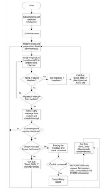
The operation of the system unfolds as follows: It commences with the initialization of all requisite variables by the software, followed by the initiation of the LCD display to signal the system’s activation. Subsequently, the system verifies the modem connection and clears the first message index within the Message Box to accommodate incoming messages. Activating the serial interrupt and ADC, it proceeds to acquire temperature readings from the LM35 sensor. These readings are then compared against a predefined threshold set at 28°C. Should the temperature exceed this threshold, the system incrementally raises the threshold to 29°C and dispatches a text message to alert the administrator, alongside activating the buzzer alarm. Otherwise, it remains in a state of readiness for a serial interrupt signaling the arrival of a new message.
Upon reception of a new text message, triggered by a serial interrupt, the system retrieves the message from the modem and verifies the sender’s phone number against the registered database. Unregistered numbers are disregarded and messages deleted, while registered numbers undergo scrutiny for correct formatting. Incorrectly formatted messages prompt a reply indicating the error, while correctly formatted messages are parsed to extract commands. These commands are then categorized as either control commands or inquiries regarding the current room temperature and relay (PORTC) status. Upon execution of either type of command, the system issues a confirmation message. The incremental adjustment of the threshold serves to prevent continuous messaging to the administrator, ensuring that subsequent messages are sent only when the temperature increases by 1°C.
Following message dispatch and buzzer deactivation (if previously activated), the system resumes its routine of modem checking and temperature readings. At this juncture, the buzzer deactivation occurs, if necessary, and the threshold is reset to 28°C if previously adjusted.
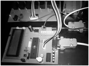
Hardware
Figure 3 displays an image of the framework. The upper portion and lower section of the illustration depict the transfer board and microcontroller board, respectively. It is evident that the GSM modem is linked to the board via a DB-9 connector.
Software
The software comprises four primary components: 1) temperature reading from the ADC, 2) text message transmission, 3) reception of text messages, and 4) parsing of text messages and command selection. Code 1 illustrates the ADC reading segment. Initially, the voltage value is extracted from PORTA(0)/ADC (0) and stored in the Adc_vlt variable. Following some computations, this value is then assigned to the Vlt variable. The Vlt variable’s value serves as the benchmark against the predefined threshold. Consequently, if the Vlt value exceeds 28°C, the system triggers an alarm.
Code1.ReaddatafromADC
Thres=28
‘…othercode…Data_adc=Getadc(0)Adc_vlt=Data_adc/1024Adc_vlt=Adc_vlt
*500
Vlt=Fusing(Adc_vlt,
The code snippet for sending text messages, depicted in Code 2, employs the AT command [10]. Within this code, the AT+CMGS command serves to dispatch text messages. A variable labeled “Number” stores the administrator’s phone number, while the message content comprises “Warning!! Room Server Temp. Now” concatenated with the current temperature value. The transmission process is initiated using Chr(26) or CTRL-Z. This segment of code is executed when the Vlt value exceeds 28°C.
Similarly, the code for receiving (reading) text messages closely resembles Code 2, albeit utilizing the AT+CMGR command.
Code2.Sendtextmessage
‘…othercode…Lcd”SendToAdmin”
Print”AT+CMGS=“;
NumberWait1
Print”Warning!!RoomServerTemp.Now“;Vlt;”‘C”
PrintChr(26)
Following the immediate parsing of messages, the selection of order choices is primarily conducted using conditional structures (if…elseif). The corresponding code segment is illustrated in Code 3 below. As depicted in the code, if the system receives the “Status” command, it proceeds to execute a separate method named Status. Additionally, the command “P1ON” is employed to alter the state of PORTC1 to ON, consequently activating the electronic device linked to one of the transistors.
Alternatively, if the command “P1OFF” is issued, the machine is shut down. Various commands are defined for the system, and these are documented in Table 1.
Code3.Commandselectionprocess
‘…othercode…
ElseifSMS_in=”Status”OrSMS_in=”status”ThenGosubStatus
ElseifSMS_in=”P1ON”OrSMS_in=”P1on”Then
Temp=1WriteeepromTemp,
1Portc.1=1GosubPortcontrol’…
Table1.Listofcommandanditsdescription
| Command | Description |
| Temp | Requestcurrent roomtemp. |
| Status | RequestthestateofPORTC(1-5)¤ttemp. |
| P#On | Changethestate ofPORTC#toON(# =1-5) |
| P#Off | Changethestate ofPORTC#toOFF(# =1-5) |
| P6Reset | PORTC6 ONforonesecondthenOFF |
| P7Reset | PORTC7 ONforonesecondthenOFF |
| PORTON | Changethestate ofPORTC# toON(#=1-5) |
| PORTOFF | Changethestate ofPORTC#toON(# =1-5) |
5. RESULT AND DISCUSSION
We conducted real-world testing of our framework within an actual server room environment. Testing procedures involved systematically sending every conceivable command to the system and meticulously observing its responses. Additionally, we evaluated the system’s reaction when subjected to incorrect message formats. Figure 4 illustrates the system being tested with the “Status” command.
The administrator dispatched a text message containing the word “Status” as its content.
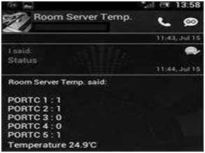
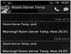
As depicted in the figure, the system provided feedback regarding the status of PORTC (1-5) and the prevailing temperature within the server room. The outcomes of this evaluation align with our anticipated outcomes. Figure 5 illustrates the notification received by the administrator when the temperature in the server room exceeds 28°C. As demonstrated, the system promptly transmitted a warning message to the administrator, detailing the current temperature of the server room. Across all testing scenarios, the system consistently operated in accordance with our specifications and expectations. Detailed testing results are outlined in Table 2.
Table 2. Testing Results
| Message sent | Reply(example) | Result |
| Temp | Temperature25.1°C | Currentroomtemperatureis sent to administrator |
| PORTC1:1 | Status of PORTC and | |
| PORTC2:1 | currentroomtemperatureis | |
| Status | PORTC3:0 | sentto administrator |
| PORTC4:0 | ||
| PORTC5:1 | ||
| Temperature25.1°C | ||
| P1On | OK P1on | PORTC1is ON |
| P1Off | OKP1off | PORTC1is OFF |
| P6Reset | OKP6reset | PORTC6 isONthen OFF |
| P7Reset | OKP7reset | PORTC7 isONthen OFF |
| PORTON | OKPorton | AllPORTC is ON |
| PORTOFF | OKPortoff | AllPORTC is OFF |
In terms of data communication, our room temperature monitoring system offers a distinct advantage compared to alternative approaches. By utilizing GSM’s short message service (SMS), our system enables administrators to conveniently check and monitor room temperature from anywhere using just a mobile phone, without requiring an internet connection. In contrast, alternative methods such as RS-485 network, Bluetooth, and Zigbee are constrained by distance limitations.
6. CONCLUSION
Within this manuscript, we present our development and deployment of a microcontroller-driven setup tailored for server room temperature monitoring. Leveraging the Atmel AVR ATmega8535 microcontroller in conjunction with the LM35 temperature sensor, we have successfully executed our design. Validation tests indicate that the system operates in accordance with our predetermined specifications.
This system serves as a valuable tool for administrators, facilitating real-time monitoring of server room temperature and remote control over electronic devices via text message (SMS), particularly beneficial when the administrator is not physically present in the server room. Furthermore, the system is equipped to issue an alert and dispatch a text message to notify the administrator in the event of elevated temperatures surpassing normal levels within the server room.
- How does the system detect temperature?
It reads voltage output from the LM35 temperature sensor via the ATmega8535 ADC and converts it to Celsius. - Does the system send alerts when temperature exceeds a threshold?
Yes, it triggers a buzzer and sends an SMS to the registered administrator when temperature exceeds 28°C. - Can the administrator control equipment remotely?
Yes, the administrator can send SMS commands to turn PORTC-connected relays ON or OFF and receive confirmations. - How does the system restrict who can send commands?
It checks the sender phone number against a stored registered number and deletes messages from unregistered numbers. - What prevents continuous alert messages when temperature hovers around the threshold?
The system increments the threshold to 29°C after sending a message to avoid continuous messaging, then resets it after conditions normalize. - Which commands can the system recognize?
Commands include Temp, Status, P#On, P#Off, P6Reset, P7Reset, PORTON, and PORTOFF as defined in the article. - How are SMS messages sent from the system?
The microcontroller uses AT commands (AT+CMGS) via the GSM modem to send messages, terminating with CTRL-Z. - How does the system read incoming SMS messages?
It uses serial interrupt handling and AT+CMGR commands to retrieve messages from the modem, then parses them for commands.