
Summary of Interfacing Dot Matrix led Display with PIC Microcontroller
Interfacing Dot Matrix led Display with PIC Microcontroller shows how to drive a 7x5 LED matrix to display the letter C by sending specific row and column bit patterns sequentially. It explains current demands when multiple LEDs in a column light simultaneously and recommends using a ULN2003A Darlington array for driving columns. A Proteus simulation is referenced and Embedded C code for a PIC microcontroller is provided to cycle through column/row data with delays to form the character.
Parts used in the Interfacing Dot Matrix led Display with PIC Microcontroller:
- 7x5 Dot Matrix LED display (7 rows x 5 columns)
- PIC microcontroller (unspecified model)
- ULN2003A Darlington transistor array IC
- Proteus simulation software (for circuit simulation)
- Wiring/connectors between rows and columns
- Power supply capable of driving the display
To know about Interfacing Dot Matrix led Display with PIC Microcontroller, we have to know about what is Dot Matrix Display? And how it work? Dot Matrix Display is an array of LED situated in a form of Matrix. See the architecture of a 7*5 Dot Matrix led Display board.

Project Description :
In this tutorial project we can see how easily we can display any alphabet in 7*5 Dot Matrix led Display board. Let we have to display letter “C” in 7*5 Dot Matrix led Display board. Now look on 7*5 Dot Matrix led Display board it has 7 rows and 5 columns. And see the every Diode connected between raw and column if raw get positive and column get negative then only particular LED will glow. Let suppose we have to glow LED connected between R5 and C1 from above picture. So we have to send 0010000 on raw and 01111 on column. Now let for display letter C which type of data we have to send

Step 1: In Raw = 0111110
In Column= 01111
Step 2: In Raw = 1000001
In Column= 10111
Step 3: In Raw = 1000001
In Column= 11011
Step 4: In Raw = 1000001
In Column= 11101
Step 5: In Raw = 0100010
In Column= 11110
For display complete alphabet “C” we have to send those data with minimum delay to display at once.
Another important think we have to keep in mind that for displaying column we need high current. because see in step 1 we are sending 0111110 so all 5 LED which have to glow in a same column so we need high current to glow all LED at a time. For this purpose we can use ULN 2003a IC which has seven built-in Darlington transistor arrays. It can provide 50volt and 500mAmp current in single chanel. In bellow I give the simulation circuit diagram In Proteus.
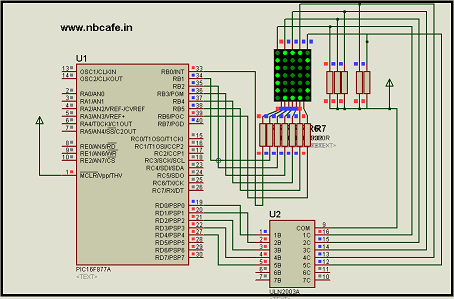
In bellow you will see the complete C code of this tutorial Interfacing Dot Matrix led Display with PIC Microcontroller for display Character “C”.
// Author : Subham Dutta
// Date : 12-03-14
// Website : www.nbcafe.in
int ch[10 ]= {254,253,251,247,239};void main() {
int i;
trisb=0;
trisd=0;
while(1)
{for(i=0;i<5;i++)
{
portb=b[i];
portd=ch[i];delay_ms(3);
}
}
}
Source : Interfacing Dot Matrix led Display with PIC Microcontroller
- What is a Dot Matrix Display?
A Dot Matrix Display is an array of LEDs arranged in a matrix, here a 7 by 5 board. - How does the 7x5 Dot Matrix LED display work?
Each LED is connected between a row and a column; an LED lights when its row is driven positive and its column is driven negative as per the required bit patterns. - How is the letter C generated on the 7x5 matrix?
By sending a sequence of row and column bit patterns for five steps as given (Step 1 to Step 5) with minimal delay to create the full character. - Why is high current needed for displaying a column?
Because multiple LEDs in the same column may need to glow simultaneously, requiring higher current to light them all at once. - Can ULN2003A be used to drive the columns?
Yes, ULN2003A with seven Darlington transistor arrays can provide up to 50 volts and 500 mA per channel and is recommended for column driving. - What code is used to display the character C?
The article provides Embedded C code that sets portb and portd with arrays b and ch and cycles through them with delay_ms(3) to display C. - Do rows and columns require specific bit patterns for individual LEDs?
Yes; for example to light the LED at R5 and C1 you would send 0010000 on the row and 01111 on the column as explained. - Is a simulation provided for this interfacing project?
Yes, a Proteus simulation circuit diagram is referenced in the article.
