
Summary of How to interface RFID with PIC18F4550 Microcontroller
RFID reader module is interfaced directly to a PIC18F4550 to receive the 12‑byte unique tag code and display it on a 16x2 LCD. The project explains using the reader in TTL mode (avoiding MAX232) and configuring the PIC USART interrupt (an internal peripheral interrupt) to capture incoming serial data. Pin functions of the RFID reader (Vcc, GND, BEEP, ANT, SEL, RS232, D1, D0) are listed and the SEL pin selects RS232 or Wiegand mode. The received tag bytes are processed and shown on the LCD.
Parts used in the RFID with PIC18F4550:
- PIC18F4550 microcontroller
- RFID Reader module (TTL output option)
- 16x2 LCD display
- Power supply 5V
- Connecting wires
- Optional: MAX232 level converter (if using RS232 mode)
RFID (Radio Frequency Identification and Detection) is widely used everywhere from highly secured defense laboratories to school attendance system. By employing RFID, much secured entry systems can be developed without incurring huge costs. These are the reasons of excessive use of RFID technology. In this article, interfacing of an RFID reader module has been explained with PIC18F4550. The USART interrupt, an internal PIC interrupt, has also been explained. (For more details on USART, refer PIC EUSART)
As explained earlier (refer RFID interfacing with 8051 & with AVR), an RFID module consists of an RFID Reader, a line converter (usually MAX232) and a COM port. The line converter of this module converts the TTL logic voltage of RFID Reader to RS232 logic. Therefore, to convert the voltage level from such an RFID module, another MAX232 is used to interface it with a microcontroller.
One can also use an RFID Reader directly to interface with the controller, thus avoiding the need of voltage level converters. Here both the MAX232s have been eliminated from the circuit and RFID reader is directly connected with the PIC microcontroller.
The following table explains the pin diagram of the RFID Reader module.
|
Pin No.
|
Name
|
Description
|
|
1
|
Vcc
|
Supply Voltage; 5V
|
|
2
|
GND
|
Ground (0V)
|
|
3
|
BEEP
|
Beep or LED drive
|
|
4
|
ANT
|
No Use
|
|
5
|
ANT
|
No Use
|
|
6
|
SEL
|
High is RS232, Low is Weigand
|
|
7
|
RS232
|
TTL output data
|
|
8
|
D1
|
Weigand Data 1
|
|
9
|
D0
|
Weigand Data 0
|
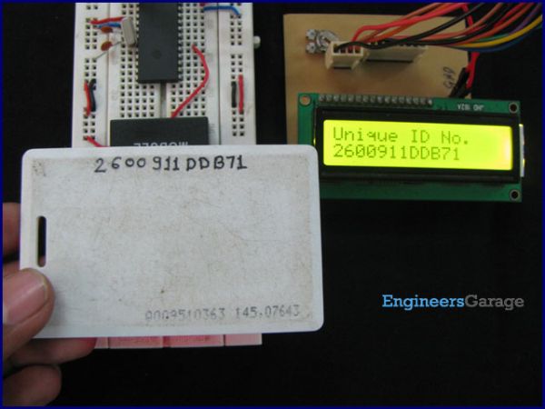
Another part of the RFID system is RFID tag, which contains 12 bytes of unique data. As the tag comes in the range of the Reader Module, it gets activated and transmits this unique code. (For more detail on working of RFID system, refer the article on RFID) The objective here is to receive this 12 byte unique code and display on a 16×2 LCD using PIC18F4550.
With the RFID interfacing, this article also explains the USART interrupt which is an internal interrupt. (For external interrupts, refer PIC Hardware interrupts) The internal interrupts, unlike hardware interrupts, are associated with internal peripherals of the controller. To use the USART interrupt, following registers have to be configured accordingly.
For more detail: How to interface RFID with PIC18F4550 Microcontroller
- Can the RFID Reader be connected directly to the PIC18F4550 without MAX232?
Yes, the article describes directly connecting the RFID Reader to the PIC by using the reader's TTL output and eliminating MAX232s. - What does the SEL pin on the RFID Reader do?
The SEL pin selects the output mode: High is RS232 and Low is Wiegand. - Which RFID Reader pin provides TTL serial data for the PIC?
The RS232 pin on the reader provides TTL output data for the microcontroller when using TTL mode. - How many bytes of unique data does an RFID tag transmit?
The RFID tag contains and transmits 12 bytes of unique data. - What is the project objective with the PIC18F4550?
The objective is to receive the 12 byte unique tag code via USART and display it on a 16x2 LCD. - Which interrupt is used to receive serial data from the RFID Reader?
The USART interrupt, an internal PIC interrupt, is used to capture incoming serial data. - Are the ANT pins on the RFID Reader used in this interfacing?
The ANT pins are marked No Use in the reader pin description provided. - Is a level converter required if the RFID Reader is outputting RS232 logic?
Yes, if the reader is outputting RS232 logic, a MAX232 level converter is needed to interface with the microcontroller.
