Introduction to the World of microcontrollers
This is how it all got started…
Microcontroller versus Microprocessor
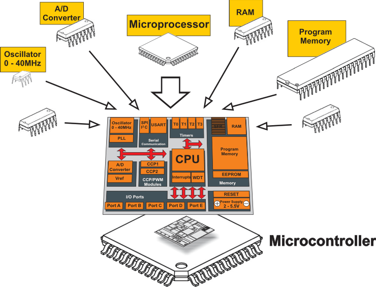
On the other hand, the microcontroller is designed to be all of that in one. No other specialized external components are needed for its application because all necessary circuits which otherwise belong to peripherals are already built into it. It saves the time and space needed to design a device.
BASIC CONCEPT
Did you know that all people can be classified into one of 10 groups- those who are familiar with binary number system and those who are not familiar with it. You don’t understand? That means that you still belong to the later group. If you want to change your status read the following text describing briefly some of the basic concepts used further in this book (just to be sure we are on the same page).
World of Numbers
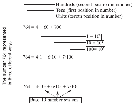
Mathematics is such a good science! Everything is so logical and simple as that. The whole universe can be described with ten digits only. But, does it really have to be like that? Do we need exactly ten digits? Of course not, it is only a matter of habit. Remember the lessons from the school. For example, what does the number 764 mean: four units, six tens and seven hundreds. Simple! Could it be described in a bit more complicated way? Of course it could: 4 + 60 + 700. Even more complicated? Naturally: 4*1 + 6*10 + 7*100. Could this number look a bit more scientific? The answer is yes: 4*10^0 + 6*10^1 + 7*10^2. What does it actually mean? Why do we use exactly these numbers: 100, 101 and 102 ? Why is it always about the number 10? That is because we use ten different digits (0, 1, 2, … 8, 9). In other words, because we use base-10 number system, i.e. decimal number system.
Binary Number System
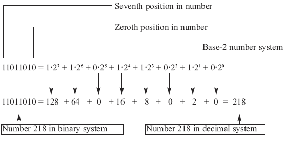
What would happen if only two digits would be used- 0 and 1? Or if we would not know to determine whether something is 3 or 5 times greater than something else? Or if we would be restricted when comparing two sizes, i.e. if we could only state that something exists (1) or does not exist (0)? Nothing special would happen, we would keep on using numbers in the same way, but they would look a bit different. For example: 11011010. How many pages of a book does the number 11011010 include? In order to learn that, follow the same logic like in the previous example, but in reverse order. Bear in mind that all this is about mathematics with only two digits- 0 and 1, i.e. base-2 number system (binary number system).
Clearly, it is the same number represented in two different ways. The only difference is in the number of digits necessary for writing some number. One digit (2) is used to write the number 2 in decimal system, whereas two digits (1 and 0) are used to write that number in binary system. Do you now agree that there are 10 groups of people? Welcome to the world of binary arithmetic! Do you have any idea where it is used? Excepting strictly controlled laboratory conditions, the most complicated electronic circuits cannot accurately determine the difference between two sizes (two voltage values, for example) if they are too small (lower than several volts). The reasons are electrical noises and something called the “real working environment” (unpredictable changes of power supply voltage, temperature changes, tolerance to values of built in components etc.). Imagine a computer which would operate upon decimal numbers by recognizing 10 digits in the following way: 0=0V, 1=5V, 2=10V, 3=15V, 4=20V… 9=45V !? Did anybody say batteries? A far simpler solution is the use of binary logic where 0 indicates that there is no voltage and 1 indicates that there is voltage. It is easier to write 0 or 1 instead of “there is no voltage” or “there is voltage”. It is called logic zero (0) and logic one (1) which electronics perfectly conforms with and easily performs all those endlessly complex mathematical operations. It is electronics which in reality applies mathematics in which all numbers are represented by two digits only and in which it is only important to know whether there is voltage or not. Of course, we are talking about digital electronics.
Hexadecimal Number System
At the very beginning of computer development it was realized that people had many difficulties in handling binary numbers. Because of this, a new numbering system had to be established. This time, a number system using 16 different digits. The first ten digits are the same as digits we are used to (0, 1, 2, 3,… 9) but there are six digits more. In order to keep from making up new symbols, the six letters of alphabet A, B, C, D, E and F are used. A hexadecimal number system consisting of digits: 0, 1, 2, 3, 4, 5, 6, 7, 8, 9, A, B, C, D, E, F has been established. What is the purpose of this seemingly bizarre combination? Just look how perfectly everything fits the story about binary numbers.
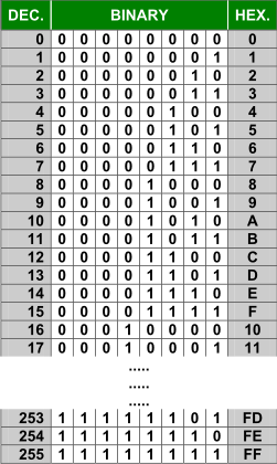
The largest number that can be represented by 4 binary digits is the number 1111. It corresponds to the number 15 in decimal system. That number is in hexadecimal system represented by only one digit F. It is the largest onedigit number in hexadecimal system. Do you see how skillfully it is used? The largest number written with eightdigits is at the same time the largest twodigit hexadecimal number. Bear in mind that the computer uses 8-digit binary numbers.
BCD Code
BCD code is actually a binary code for decimal numbers only. It is used to enable electronic circuits to communicate in a decimal number system with peripherals and in a binary system within “their own world”. It consists of fourdigit binary numbers which represent the first ten digits (0, 1, 2, 3 … 8, 9). Even though four digits can give a total of 16 possible combinations, only the first ten are used.
Number System Conversion
The binary numbering system is the most commonly used, the decimal system is the most understandable while the hexadecimal system is somewhere between them. Therefore, it is very important to learn how to convert numbers from one numbering system to another, i.e. how to turn a series of zeros and units into values understandable to us.
Binary to Decimal Number Conversion
Digits in a binary number have different values depending on their position in that number. Additionally, each position can contain either 1 or 0 and its value may be easily determined by its position from the right. To make the conversion of a binary number to decimal it is necessary to multiply values with the corresponding digits (0 or 1) and add all the results. The magic of binary to decimal number conversion works…You doubt? Look at the example: 110 = 1*2^2 + 1*2^1 + 0*2^0 = 6 It should be noted that for decimal numbers from 0 to 3 you only need two binary digits. For greater values, extra binary digits must be added. Thus, for numbers from 0 to 7 you need three digits, for numbers from 0 to 15- four digits etc. Simply speaking, the largest binary number consisting of n digits is obtained when the base 2 is raised by n. The result should be then subtracted by 1. For example, if n=4: 2^4 – 1 = 16 – 1 = 15 Accordingly, using 4 binary digits it is possible to represent decimal numbers from 0 to 15, including these two digits, which amounts to 16 different values in total.
Hexadecimal to Decimal Number Conversion
In order to make conversion of a hexadecimal number to decimal, each hexadecimal digit should be multiplied with the number 16 raised by its position value. For example:
Marking Numbers
The hexadecimal numbering system is along with binary and decimal number systems considered to be the most important for us. It is easy to make conversion of any hexadecimal number to binary and it is also easy to remember it. However, these conversions may cause confusion. For example, what does the statement “It is necessary to count up 110 products on assembly line” actually mean? Depending on whether it is about binary, decimal or hexadecimal, the result could be 6, 110 or 272 products, respectively! Accordingly, in order to avoid misunderstanding, different prefixes and suffixes are directly added to the numbers. The prefix $ or 0x as well as the suffix h marks the numbers in hexadecimal system. For example, hexadecimal number 10AF may look as follows $10AF, 0x10AF or 10AFh. Similarly, binary numbers usually get the suffix % or 0b, whereas decimal numbers get the suffix D.
Byte
A byte or a program word consists of eight bits grouped together. If a bit is a digit, it is logical that bytes represent numbers. All mathematical operations can be performed upon them, like upon common decimal numbers. As is the case with digits of any other number, byte digits do not have the same significance. The largest value has the leftmost bit called the most significant bit (MSB). The rightmost bit has the least value and is therefore called the least significant bit (LSB). Since eight zeros and units of one byte can be combined in 256 different ways, the largest decimal number which can be represented by one byte is 255 (one combination represents zero). A nibble is referred to as half a byte. Depending on which half of the byte we are talking about (left or right), there are “high” and “low” nibbles.

AND Gate
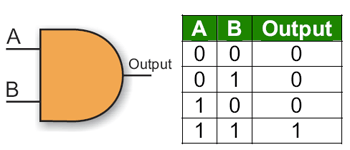
A logic gate “AND” has two or more inputs and one output. Let us presume that the gate used in this case has only two inputs. A logic one (1) will appear on its output only in case both inputs (A AND B) are driven to logic one (1).
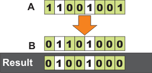
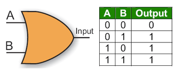
OR Gate
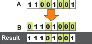

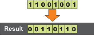
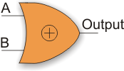
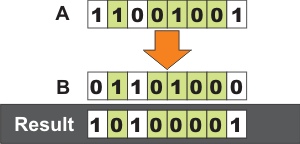
Register
A register or a memory cell is an electronic circuit which can memorize the state of one byte.
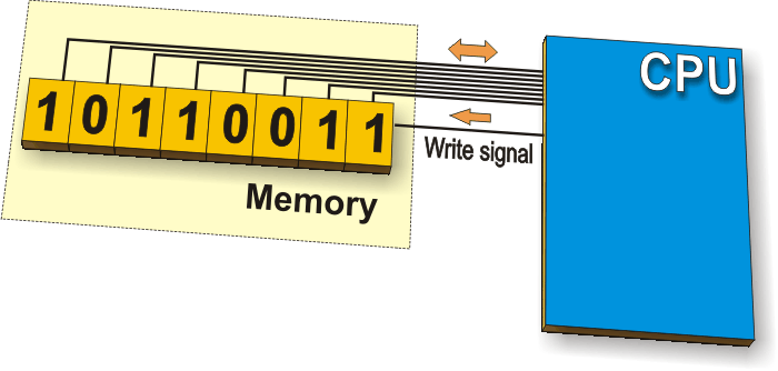
Special Function Register
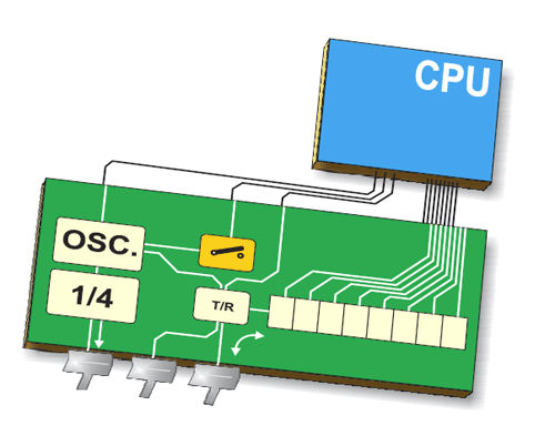
In addition to the registers which do not have any special and predetermined function, every microcontroller has a number of registers whose function is predetermined by the manufacturer. Their bits are connected (literally) to internal circuits such as timers, A/D converter, oscillators and others, which means that they are directly in command of the operation of the microcontroller. Imagine eight switches which are in command of some smaller circuits within the microcontroller- you are right! Special Function Registers (SFRs) do exactly that!
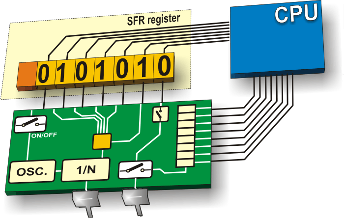
Input/Output Ports
In order to make the microcontroller useful, it has to be connected to additional electronics, i.e. peripherals. Each microcontroller has one or more registers (called a “port”) connected to the microcontroller pins. Why input/output? Because you can change the pin’s function as you wish. For example, suppose you want your device to turn three signal LEDs and simultaneously monitor the logic state of five sensors or push buttons. Some of ports need to be configured so that there are three outputs (connected to the LEDs) and five inputs (connected to sensors). It is simply performed by software, which means that the pin’s function can be changed during operation.
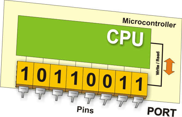
One of the more important specifications of input/output (I/O) pins is the maximum current they can handle. For most microcontrollers, current obtained from one pin is sufficient to activate an LED or other similar low-current device (10-20 mA). If the microcontroller has many I/O pins, then the maximum current of one pin is lower. Simply put, you cannot expect all pins to give maximum current if there are more than 80 of them on one microcontroller. Another way of putting it is that the maximum current stated in the data specifications sheet for the microprocessor is shared across all I/O ports. Another important pin function is that it can have pull-up resistors. These resistors connect pins to the positive power supply voltage and their effect is visible when the pin is configured as an input connected to mechanical switch or push button. Newer versions of microcontrollers have pull-up resistors configurable by software. Usually, each I/O port is under control of another SFR, which means that each bit of that register determines the state of the corresponding microcontroller pin. For example, by writing logic one (1) to one bit of that control register SFR, the appropriate port pin is automatically configured as input. It means that voltage brought to that pin can be read as logic 0 or 1. Otherwise, by writing zero to the SFR, the appropriate port pin is configured as an output. Its voltage (0V or 5V) corresponds to the state of the appropriate bit of the port register.
Memory Unit
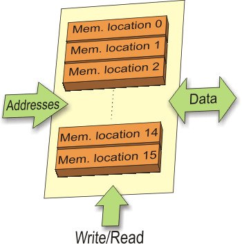
Memory is part of the microcontroller used for data storage. The easiest way to explain it is to compare it with a filing cabinet with many drawers. Suppose, the drawers are clearly marked so that it is easy to access any of them. It is easy enough to find out the contents of the drawer by reading the label on the front of the drawer.
Read Only Memory (ROM)
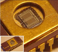
ROM (Read Only Memory) is used to permanently save the program being executed. The size of a program that can be written depends on the size of this memory. Today’s microcontrollers commonly use 16-bit addressing, which means that they are able to address up to 64 Kb of memory, i.e. 65535 locations. As a novice, your program will rarely exceed the limit of several hundred instructions. There are several types of ROM. Masked ROM. Microcontrollers containing this ROM are reserved for the great manufacturers. Program is loaded into the chip by the manufacturer. In case of large scale manufacture, the price is very low. Forget it… One Time Programmable ROM (OTP ROM). If the microcontroller contains this memory, you can download a program into this memory, but the process of program downloading is a “one-way ticket”, meaning that it can be done only once. If an error is detected after downloading, the only thing you can do is to download the corrected program to another chip.
Interrupt
The most programs use interrupts in regular program execution. The purpose of the microcontroller is mainly to react on changes in its surrounding. In other words, when some event takes place, the microcontroller does something… For example, when you push a button on a remote controller, the microcontroller will register it and respond to the order by changing a channel, turn the volume up or down etc. If the microcontroller spent most of its time endlessly a few buttons for hours or days… It would not be practical. The microcontroller has learnt during its evolution a trick. Instead of checking each pin or bit constantly, the microcontroller delegates the “wait issue” to the “specialist” which will react only when something attention worthy happens. The signal which informs the central processor about such an event is called an INTERRUPT.
Central Processor Unit (CPU)
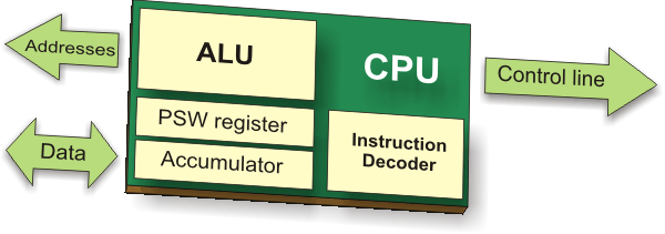
As its name suggests, this is a unit which monitors and controls all processes inside the microcontroller. It consists of several smaller subunits, of which the most important are:
- Instruction Decoder is a part of the electronics which recognizes program instructions and runs other circuits on the basis of that. The “instruction set” which is different for each microcontroller family expresses the abilities of this circuit.
- Arithmetical Logical Unit (ALU) performs all mathematical and logical operations upon data.
- Accumulator is a SFR closely related to the operation of the ALU. It is a kind of working desk used for storing all data upon which some operation should be performed (addition, shift/move etc.). It also stores the results ready for use in further processing. One of the SFRs, called a Status Register (PSW), is closely related to the accumulator. It shows at any given moment the “status” of a number stored in the accumulator (number is greater or less than zero etc.).
Bus
Physically, the bus consists of 8, 16 or more wires. There are two types of buses: the address bus and the data bus. The address bus consists of as many lines as necessary for memory addressing. It is used to transmit the address from the CPU to the memory. The data bus is as wide as the data, in our case it is 8 bits or wires wide. It is used to connect all circuits inside the microcontroller.
Serial Communication
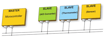
Parallel connections between the microcontroller and peripherals via input/output ports is the ideal solution for shorter distances- up to several meters. However, in other cases – when it is necessary to establish communication between two devices on longer distances it is not possible to use a parallel connection – such a simple solution is out of question. In these situations, serial communication is the best solution. Today, most microcontrollers have built in several different systems for serial communication as a standard equipment. Which of these systems will be used depends on many factors of which the most important are:
- How many devices the microcontroller has to exchange data with?
- How fast the data exchange has to be?
- What is the distance between devices?
- Is it necessary to send and receive data simultaneously?
One of the most important things concerning serial communication is the Protocol which
should be strictly observed. It is a set of rules which must be applied in order that the devices can correctly interpret data they mutually exchange. Fortunately, the microcontrollers automatically take care of this, so the work of the programmer/user is reduced to simple write (data to be sent) and read (received data).
Baud Rate
The term Baud rate is commonly used to denote the number of bits transferred per second [bps]. It should be noted that it refers to bits, not bytes! It is usually required by the protocol that each byte is transferred along with several control bits. It means that one byte in serial data stream may consist of 11 bits. For example, if the baud rate is 300 bps then maximum 37 and minimum 27 bytes may be transferred per second, which depends on type of connection and protocol in use. The most commonly used serial communication systems are:

Oscillator
Power supply circuit
There are two things worth attention concerning the microcontroller power supply circuit: Brown-out is a potentially dangerous state which occurs at the moment the microcontroller is being turned off or in situations when power supply voltage drops to the limit due to electric noise. As the microcontroller consists of several circuits which have different operating voltage levels, this state can cause its out-of-control performance. In order to prevent it, the microcontroller usually has built-in circuit for brown out reset. This circuit immediately resets the whole electronics when the voltage level drops below the limit. Reset pin is usually marked as MCLR (Master Clear Reset) and serves for external reset of the microcontroller by applying logic zero (0) or one (1), depending on type of the microcontroller. In case the brown out circuit is not built in, a simple external circuit for brown out reset can be connected to this pin.
Timers/Counters
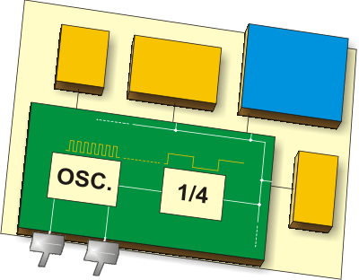
The microcontroller oscillator uses quartz crystal for its operation. Even though it is not the simplest solution, there are many reasons to use it. Namely, the frequency of such oscillator is precisely defined and very stable, the pulses it generates are always of the
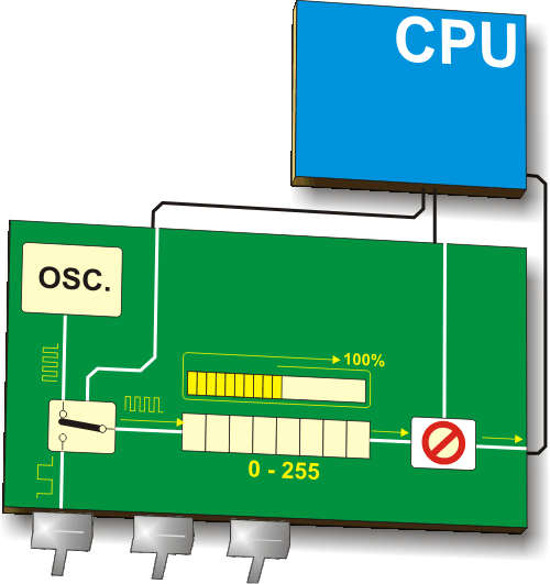
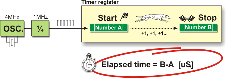
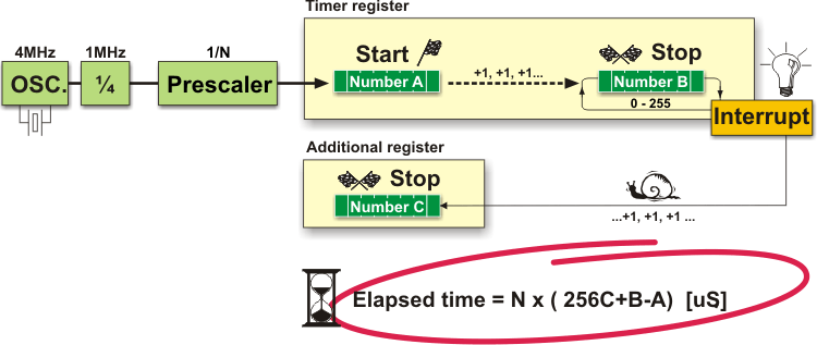
same width, which makes them ideal for time measurement. Such oscillators are used in quartz watches. If it is necessary to measure time between two events, it is sufficient to count pulses coming from this oscillator. That is exactly what the timer does. Most programs use these miniature electronic “stopwatches”. These are commonly 8- or 16-bit SFRs and their content is automatically incremented by each coming pulse. Once a register is completely loaded – an interrupt is generated! If the timer registers use an internal quartz oscillator for their operation then it is possible to measure time between two events (if the register value is T1 at the moment measurement has started, and T2 at the moment it has finished, then the elapsed time is equal to the result of subtraction T2-T1). If the registers use pulses coming from external source then such a timer is turned into a counter. This is only a simple explanation of the operation itself.
How does a timer operate?
In practice pulses coming from the quartz oscillator are once per each machine cycle directly or via a prescaler brought to the circuit which increments the number in the timer register. If one instruction (one machine cycle) lasts for four quartz oscillator periods then, by embedding quartz with the frequency of 4MHz, this number will be changed a million times per second (each microsecond).
Using prescaler in timer operating
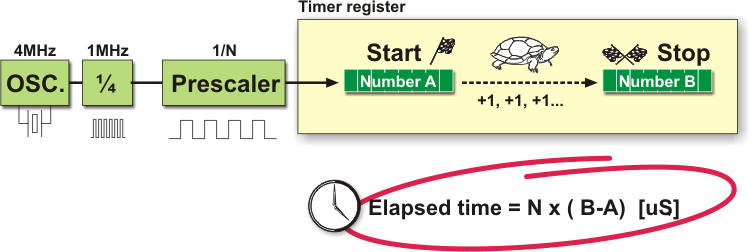
A prescaler is an electronic device used to reduce a frequency by a pre-determined factor. Meaning that in order to generate one pulse on its output, it is necessary to bring 1, 2 , 4 or more pulses to its input. One such circuit is built in the microcontroller and its division rate can be changed from within the program. It is used when it is necessary to measure longer periods of time. One prescaler is usually shared by timer and watch-dog timer, which means that it cannot be used by both of them simultaneously.
Using the interrupt in timer operation
If the timer register consists of 8 bits, the largest number that can be written to it is 255 (for 16-bit registers it is the number 65.535). If this number is exceeded, the timer will be automatically reset and counting will start from zero again. This condition is called overflow. If enabled from within the program, such overflow can cause an interrupt, which gives completely new possibilities. For example, the state of registers used for counting seconds, minutes or days can be changed in an interrupt routine. The whole process (except interrupt routine) is automatically performed “in the background”, which enables the main circuits of the microcontroller to perform other operations.
Counters
If a timer is supplying pulses into the microcontroller input pin then it turns into a counter. Clearly, It is the same electronic circuit. The only difference is that in this case pulses to be counted come through the ports and their duration (width) is mostly not defined. This is why they cannot be used for time measurement, but can be used to measure anything else: products on an assembly line, number of axis rotation, passengers etc. (depending on sensor in use).
Watchdog Timer
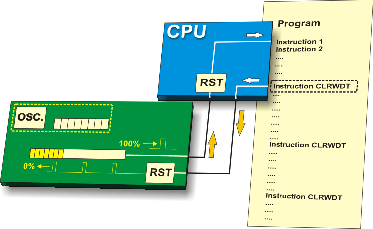
The Watchdog Timer is a timer connected to a completely separate RC oscillator within the microcontroller. If the watchdog timer is enabled, every time it counts up to the program end, the microcontroller reset occurs and program execution starts from the first instruction. The point is to prevent this from happening by using a specific command. The whole idea is based on the fact that every program is executed in several longer or shorter loops. If instructions which reset the watchdog timer are set at the appropriate program locations, besides commands being regularly executed, then the operation of the watchdog timer will not affect program execution. If for any reason (usually electrical noises in industry), the program counter “gets stuck” on some memory location from which there is no return, the watchdog will not be cleared and the register’s value being constantly incremented will reach the maximum et voila! Reset occurs!
A/D Converter
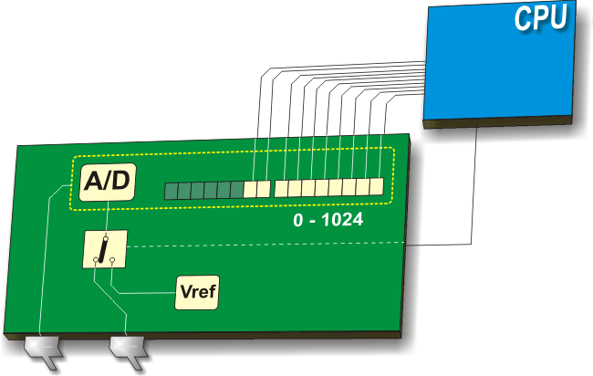
External signals are usually fundamentally different from those the microcontroller understands (Ones and Zeros), so that they have to be converted in order for the microcontroller to understand them. An analogue to digital converter is an electronic circuit which converts continuous signals to discrete digital numbers. This module is therefore used to convert some analogue value into binary number and forwards it to the CPU for further processing. In other words, this module is used for input pin voltage measurement (analogue value). The result of measurement is a number (digital value) used and processed later in the program.
Internal Architecture
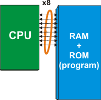
All upgraded microcontrollers use one of two basic design models called Harvard and von-Neumann architecture. Briefly, they are two different ways of data exchange between CPU and memory. von-Neumann Architecture
- Read the part of the program instruction specifying WHAT should be done (in this very case it is the “incf” instruction for increment).
- Read further the same instruction specifying upon WHICH data it should be performed (in this very case it is the “SUM” register).
- After being incremented, the contents of this register should be written to the register from which it was read (“SUM” register address).
The same data bus is used for all these intermediate operations. Harvard Architecture
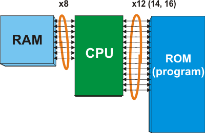
- All data in a program is one byte (8 bit) wide. As the data bus used for program reading has several lines (12, 14 or 16), both instructions and data can be read simultaneously by using these spare bits. Therefore, all instructions are executed in only one instruction cycle. The only exception is jump instruction which is executed in two cycles.
- Owing to the fact that a program (ROM) and temporary data (RAM) are separate, the CPU can execute two instructions simultaneously. Simply, while RAM read or write is in progress (the end of one instruction), the next program instruction is being read via another bus.
- When using microcontrollers with von-Neumann architecture one never knows how much memory is to be occupied by some program. Basically, each program instruction occupies two memory locations (one contains information on WHAT should be done, whereas another contains information upon WHICH data it should be done). However, it is not a hard and fast rule, but the most common case. In microcontrollers with Harvard architecture, the program bus is wider than one byte, which allows each program word to consist of instruction and data. In other words: one program word- one instruction.
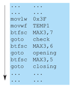
INSTRUCTION SET
How to make the right choice
Ok, you are the beginner and you have made a decision to go on an adventure of working with the microcontrollers. Congratulations on your choice! However, it is not as easy to choose the right microcontroller as it may seem. The problem is not a limited range of devices, but the opposite! Before you start designing some device based on the microcontroller, think of the following: how many input/output lines will I need for operation? Should it perform some other operations than to simply turn relays on/off? Does it need some specialized module such as serial communication, A/D converter etc. When you create a clear picture of what you need, the selection range is considerably reduced, then it is time to think of price. Is your plan to have several same devices? Several hundred? A million? Anyway, you get the point… If you think of all these things for the very first time then everything seems a bit confusing. For that reason, go step by step. First of all, select the manufacturer, i.e. the family of the microcontrollers you can easily obtain. After that, study one particular model. Learn as much as you need, do not go into details. Solve a specific problem and something incredible will happen- you will be able to handle any model belonging to that family. Remember learning to ride a bicycle: after several unavoidable bruises at the beginning, you will manage to keep balance and will be able to easily ride any other bicycle. And of course, you will never forget the skill in programming just as you will never forget riding bicycles!
PIC microcontrollers
PIC microcontrollers designed by Microchip Technology are likely the right choice for you if you are the beginner. Here is why… The real name of this microcontroller is PICmicro (Peripheral Interface Controller), but it is better known as PIC. Its first ancestor was designed in 1975 by General Instruments. This chip called PIC1650 was meant for totally different purposes. About ten years later, by adding EEPROM memory, this circuit was transformed into a real PIC microcontroller. Nowadays, Microchip Technology announces a manufacturing of the 5 billionth sample… In order that you can better understand the reasons for its popularity, we will briefly describe several important things.
| Family | ROM [Kbytes] | RAM [bytes] | Pins | Clock Freq. [MHz] | A/D Inputs | Resolution of A/D Converter | Compar- ators | 8/16 – bit Timers | Serial Comm. | PWM Outputs | Others |
| Base-Line 8 – bit architecture, 12-bit Instruction Word Length | |||||||||||
| PIC10FXXX | 0.375 – 0.75 | 16 – 24 | 6 – 8 | 4 – 8 | 0 – 2 | 8 | 0 – 1 | 1 x 8 | – | – | – |
| PIC12FXXX | 0.75 – 1.5 | 25 – 38 | 8 | 4 – 8 | 0 – 3 | 8 | 0 – 1 | 1 x 8 | – | – | EEPROM |
| PIC16FXXX | 0.75 – 3 | 25 – 134 | 14 – 44 | 20 | 0 – 3 | 8 | 0 – 2 | 1 x 8 | – | – | EEPROM |
| PIC16HVXXX | 1.5 | 25 | 18 – 20 | 20 | – | – | – | 1 x 8 | – | – | Vdd = 15V |
| Mid-Range 8 – bit architecture, 14-bit Instruction World Length | |||||||||||
| PIC12FXXX | 1.75 – 3.5 | 64 – 128 | 8 | 20 | 0 – 4 | 10 | 1 | 1 – 2 x 8 1 x 16 | – | 0 – 1 | EEPROM |
| PIC12HVXXX | 1.75 | 64 | 8 | 20 | 0 – 4 | 10 | 1 | 1 – 2 x 8 1 x 16 | – | 0 – 1 | – |
| PIC16FXXX | 1.75 – 14 | 64 – 368 | 14 – 64 | 20 | 0 – 13 | 8 or 10 | 0 – 2 | 1 – 2 x 8 1 x 16 | USART I2C SPI | 0 – 3 | – |
| PIC16HVXXX | 1.75 – 3.5 | 64 – 128 | 14 – 20 | 20 | 0 – 12 | 10 | 2 | 2 x 8 1 x 16 | USART I2C SPI | – | – |
| High-End 8 – bit architecture, 16-bit Instruction Word Length | |||||||||||
| PIC18FXXX | 4 – 128 | 256 – 3936 | 18 – 80 | 32 – 48 | 4 – 16 | 10 or 12 | 0 – 3 | 0 – 2 x 8 2 – 3 x 16 | USB2.0 CAN2.0 USART I2C SPI | 0 – 5 | – |
| PIC18FXXJXX | 8 – 128 | 1024 – 3936 | 28 – 100 | 40 – 48 | 10 – 16 | 10 | 2 | 0 – 2 x 8 2 – 3 x 16 | USB2.0 USART Ethernet I2C SPI | 2 – 5 | – |
| PIC18FXXKXX | 8 – 64 | 768 – 3936 | 28 – 44 | 64 | 10 – 13 | 10 | 2 | 1 x 8 3 x 16 | USART I2C SPI | 2 | – |
All PIC microcontrollers use harvard architecture, which means that their program memory is connected to CPU via more than 8 lines. Depending on the bus width, there are 12-, 14- and 16-bit microcontrollers. The table above shows the main features of these three categories. As seen in the table on the previous page, excepting “16-bit monsters”- PIC 24FXXX and PIC 24HXXX- all PIC microcontrollers have 8-bit harvard architecture and belong to one out of three large groups. Therefore, depending on the size of a program word there are first, second and third category, i.e. 12-, 14- or 16-bit microcontrollers. Having similar 8- bit core, all of them use the same instruction set and the basic hardware ‘skeleton’ connected to more or less peripheral units. In order to avoid tedious explanations and endless story about the useful features of different microcontrollers, this book describes the operation of one particular model belonging to “high middle class”. It is about PIC16F887- powerful enough to be worth attention and simple enough to be easily presented to everybody.
Source : PIC Microcontrollers by Milan Verle

