
Summary of Voice Activated Power Sockets (Home Automation)
This project implements a voice-controlled home automation system that uses PC-based speech recognition to trigger a microcontroller (PIC or Arduino) via serial/RS232, which drives a relay to switch mains appliances on or off. The author used off-the-shelf components (speech recognition software Tazti, PIC-MT board with PIC16F876A, bootloader, and a C serial client) to map custom voice commands (e.g., TV ON/TV OFF) to relay control, with firmware on the PIC handling incoming command words.
Parts used in the Voice Activated Power Sockets (Home Automation):
- PC or Laptop running Microsoft Windows
- Microphone (internal or external)
- Speech recognition software (Tazti)
- C program acting as Serial/RS232 driver/client
- PIC microcontroller development board (PIC-MT from Olimex) with serial/RS232 interface and on-board relay
- PIC16F876A microcontroller
- Transistor to drive the relay (onboard)
- Relay to switch the electrical appliance
- PIC bootloader and downloader software (from Sparkfun)
- PIC programmer (for initial bootloader programming, e.g., PIC Start Plus)
Yet another voice controlled home automation system!
As shown in the picture, the system can control any electrical appliance, by turning ON or OFF, that is connected into the electrical socket. The system does this using bespoke voice commands. The system uses a micro-controller board (PIC or Arduino) and a PC/Laptop with the Microsoft Windows Operating System.
Motivation
I always wanted to make a system that worked on my voice commands. I started working on this project to realize my dream to be able to control gadgets/appliances with my voice commands. I made this project at home from my electronics laboratory in my garage and in my holiday time and on weekends.
Disclaimer
1) Please note that since this project involves controlling of electrical appliances running at very high voltage (230V AC), please do so carefully and at your own risk.
2) All the instructions and code are provided “as is”, please follow/use them at your own risk, I will not be liable for anything what so ever.
3) Also please let me inform you that I do not have any tie-up with the vendors that I have mentioned below from whom I have acquired, obtained, purchased various software and hardware components, nor do I receive any commission from them. These components carry license agreements from the vendors. Please adhere to their respective license agreements.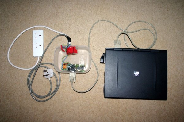
Step 1: Project Theme: ! (Re-Inventing the Wheel)
I strongly believe in not “re-inventing the wheel” therefore most of the components that I have used are off-the-shelf (Hw/Sw both). This enables anybody to create this project very quickly without requiring in depth technical knowledge about electronic circuits and without worrying about the complexity of speech recognition.
This project is more of an innovation hobby project. The components that I required to build a basic speech recognition based home automation system were a speech recognition software, a PC or an embedded computer with an internal or external microphone to run the speech recognition software, an electronic circuit to control the power to an electrical appliance or a gadget.
Step 2: System Design
The way this automation system is designed and works is as shown in the figure. When a voice command (any voice command that I like) is uttered, it is recognized by a speech recognition software running on a PC with a microphone. The speech recognition software then invokes a ‘C’ program, i.e. Serial port driver, that sends a command over to the PC serial port to which a micro-controller board is interfaced. The micro-controller on the board runs a firmware that receives the command from the serial port and interprets it. The micro-controller then toggles an output pin which drives a transistor which in turn drives a relay. The relay then controls any appliance that is connected to it. The figure shows the complete system design.
Step 3: Finding the Right Speech Recognition System
The very first thing that I required was a speech recognition system that would allow me implement my own commands and train my voice on the same commands. In other words I wanted the functionality where the system would accept my own customized voice commands and upon recognizing the commands the system would then run an executable or a program that I have implemented. While I was looking for such system on the internet, I stumbled upon a PC based speech recognition system called “TAZTI”. I selected this software as the speech recognition front end is because it satisfied the main two requirements: firstly it allows the user to create their own custom voice commands and secondly the system allows user to run their own program or executable upon recognizing these commands. There are quite a few other useful features in the Tazti speech recognition software (can be obtained from their website www.tazti.com ). Older versions of the software were freeware but the current versions are paid however they do provide a trial version for 15 days.
Step 4: Interfacing with the PC
The second thing that I needed was a way to interface an electrical appliance with the PC using possibly the parallel or the serial or the USB port . So when a voice command is recognized in the PC a program would be executed which then sent a control command to the interfacing circuit to activate or de-activate a relay that controlled the electrical appliance or the gadget. I chose to use an off-the-shelf PIC micro-controller board that also had a relay and a serial port interface on the same board. You could use any such micro-controller board for an example Arduino.
While looking for such micro-controller board I came across PIC-MT a development board for 28 pin PIC microcontroller from Olimex (can be obtained from their website www.olimex.com ). This board comes with a Serial/RS232 interface which can directly be connected to a PC serial port and an on-board circuit with a relay. All the details about the board such as schematic/circuit diagram and user manual etc are available from their website. I used PIC 16F876A for my prototype and implemented the firmware for the micro-controller in ‘C’. I have also used the PIC boot loader and downloader software from Sparkfun (from www.sparkfun.com ). The boot loader allowed me to download the firmware in hex in to the program memory of the micro-controller over the serial port of the PC without requiring a proper PIC programmer and the special board socket for PIC programmers. Also this was carried out while keeping the micro-controller in the chip socket on the board, i.e. ICSP (In Circuit Serial Programming). Although I did have to program the boot loader for the very first time using the PIC programmer (PIC Start Plus or similar) into the micro-controller.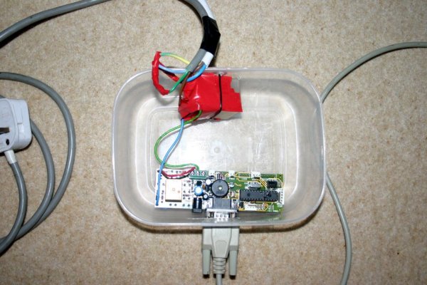
Step 5: PC Serial Driver/Client Program
I implemented a simple ‘C’ program (essentially a Serial/RS232 driver and a client program) for the PC which would send a control command over to the serial port to the PIC board whenever this program is executed. The PIC serial server program would then listen to the commands arriving on the serial port and upon recognizing a control command it would perform a task(s) such as turning ON the relay or turning OFF the relay.
The attached ‘C’ Serial/RS232 driver/client program sends command word 27 to the PIC board. I programed the voice command to be “TV ON”. This code has been successfully tested on Windows XP. For the voice command “TV OFF” the command word was 28. This ‘C’ program is in older style, shown here as an example, more modern Win32 user mode driver program could easily be written using Windows API for accessing serial port.
For more detail: Voice Activated Power Sockets (Home Automation)
- What does the system use to recognize voice commands?
The system uses PC-based speech recognition software (Tazti) running on a Windows PC with a microphone. - How are recognized commands sent to the microcontroller?
The speech recognition software runs a C program that sends command words over the PC serial/RS232 port to the PIC microcontroller board. - Which microcontroller board was used in the project?
The project used the PIC-MT development board from Olimex with a PIC16F876A microcontroller. - Can the system control any appliance?
Yes, any electrical appliance plugged into the relay-controlled socket can be turned ON or OFF by the system. - How does the microcontroller activate the appliance?
The microcontroller toggles an output pin that drives a transistor which in turn drives a relay that controls the appliance. - What voice commands were used in the example?
The example used the voice commands TV ON and TV OFF mapped to command words 27 and 28 respectively. - Is special programming hardware required to download firmware?
The author used a PIC bootloader and downloader to program firmware via serial port, though the bootloader was initially programmed using a PIC programmer like PIC Start Plus. - Does the project require building custom speech recognition?
No, the project uses off-the-shelf speech recognition software that allows custom commands and running executables upon recognition.
