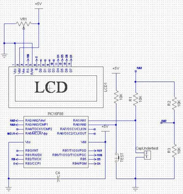
When TEST botton is pressed, RA3 pin is set to “1”. R2 and R3 are divide the voltage to 1/2 Vra3 which is connected to RA2 pin to be a Vref for comparator. The C undertest is charging and the timer is start. When the voltage of C undertest is more than 1/2 or above Vref, the timer is stop. and a number of periods that elapsed multiply by 10 is the C value in nF. Convert C number to string and display to 1×16 LCD.
The code
/*
* Project name:
Capacitance Meter
* Copyright:
Nicholas Sirirak
* Description:
* Test configuration:
MCU: PIC16F88
Dev.Board: –
Oscillator: HS, 8.0000 MHz internal
Ext. Modules: –
SW: mikroC v8.1.0.0
* NOTES:
*/
#define Vappied PORTA.F3
#define TEST PORTA.F0
unsigned int gCap = 0;
char gOverTest = 0;
char gMessage[8];
char gCapstr[8];
void interrupt(){
if(PIR1.TMR2IF){
TMR2 = 0x87; // best value to create 69.3us
gCap++;
if(gCap > 65500) gOverTest = 1;
PIR1.TMR2IF =0; // Clear int bit
}
}
void main(){
char i,j;
char cap_size;
ANSEL = 0;
TRISB = 0;
PORTB = 0;
OSCCON = 0x7E; // 8Mhz, RC internal clock
OPTION_REG.T0CS = 0;
INTCON.GIE = 1; //Enable global interrupt
INTCON.PEIE = 1; //Enable peripheral interrupt
//———— Set up Timer2 ————
PIE1.TMR2IE = 1;
T2CON = 0; // timer2 off, prescaler 1:1
TMR2 = 0x87;
PIR1.TMR2IF =0; // Clear int bit
//—————————————-
For more detail: Determine capacitance by measuring the charging time using PIC16F688

