
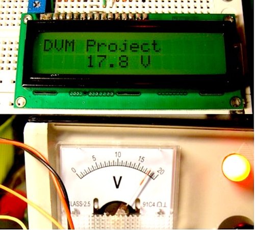
Summary of Simple Digital Voltmeter (DVM) using PIC12F675 (Code+Proteus simulation)
This post describes a simple 0–5V digital voltmeter using a PIC12F675 microcontroller. ADC on GP4 (AN3) reads input voltage; GP0–GP2 drive an LCD to display the measured voltage. A potentiometer can simulate the input; the code (C, HI-TECH C, MPLAB) samples every 0.5 seconds and displays values like 2.50V. Proteus simulation and downloadable code/proteus files are provided.
Parts used in the Simple Digital Voltmeter:
- PIC12F675 microcontroller
- LCD (character display)
- Potentiometer (for input simulation)
- Wiring / breadboard or PCB
- Power supply (0–5V)
- MPLAB with HI-TECH C compiler (software tool)
- Proteus (simulation software)
This post provides a simple digital voltmeter circuit using PIC12F675 microcontroller. This code is written in C language using MPLAB with HI-TECH C compiler. You can download this code from the ‘Downloads‘ section at the bottom of this page.
In this post, it is assumed that you know,
- How to use ADC of PIC12F675 microcontroller. If you don’t then please read this page.
- How to interface LCD with PIC12F675 microcontroller. If you don’t then please read this page.
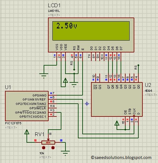
The result of simulating the code in Proteus is shown below.
In this circuit GP0, GP1 and GP2 pins are used to interface LCD with PIC12F675 microcontroller[1]. The input to the digital voltmeter is given on the GP4 (or AN3) pin. In the above figure, a potentiometer is used to simulate any voltage (from 0v to 5v range) on the digital voltmeter input. In this figure, potentiometer is set at 50% value and this means a voltage of 2.5v is present at pin3 of PIC12F675 microcontroller. This voltage is read using ADC conversion and it’s value is displayed on the LCD, so a correct value of 2.50v is shown on the LCD. You can read any voltage from 0v to 5v with this digital voltmeter. In this code, after every half second new value is read from pin3 and is displayed on the LCD[2].
Code
The main function code is shown below.
Downloads
Digital voltmeter code using PIC12F675 was compiled in MPLAB v8.85 with HI-TECH C v9.83 compiler and simulation was made in Proteus v7.10. To download code and Proteus simulationclick here.
For more detail: Simple Digital Voltmeter (DVM) using PIC12F675 (Code+Proteus simulation)
- What microcontroller is used in the project?
The project uses a PIC12F675 microcontroller. - Which pins are used to interface the LCD?
GP0, GP1 and GP2 pins are used to interface the LCD with PIC12F675. - Which pin is used for the voltmeter input?
The input voltage is given to GP4 (AN3) pin. - What input voltage range can the voltmeter read?
The voltmeter can read voltages from 0 V to 5 V. - How often does the code update the displayed value?
The code reads a new value and updates the LCD every half second. - What tools were used to compile and simulate the project?
Code was compiled in MPLAB v8.85 with HI-TECH C v9.83 and simulated in Proteus v7.10. - How is a test input voltage provided in the simulation?
A potentiometer is used in the simulation to provide any voltage between 0 V and 5 V. - What display format is shown for the measured voltage?
The voltage is displayed on the LCD with two decimal places, for example 2.50 V.
