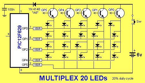
This project drives a number of LEDs via a very clever circuit.
There are 3 ways to dive a LED from an output of a micro.
The simplest is called “dump.”
This is where the LED is connected directly to the output via a resistor and when the output is HIGH, the LED illuminates. But if the micro has 5 outputs, only 5 LEDs can be illuminated.
A LED will only illuminate when the voltage is applied in the right direction.
We can take advantage of this and connect 2 LEDs across each other with one LED in the opposite direction.
When voltage is applied, one LED will illuminate and when the voltage is reversed, the other LED will illuminate. This will allow us to illuminate more than 5 LEDs.
But if the LED-pairs are connected to the outputs as shown in the diagram below, up to 20 LEDs can be driven from 5 lines. However only 2 LEDs can be on at any one time and these LEDs produce full brightness.
If you turn on the wrong set of output lines, more LEDs will illuminate but the 25mA capability of each line will be shared between the LEDs.
Since only two LEDs can be on at the same time, the duty cycle is 10%.
Another way to drive 20 LEDs is via MULTIPLEXING.
This is the same as SCANNING.
To turn on LEDs 11,2,3,4, the drive lines are made LOW and the fifth line is taken to a transistor. When the fifth line is taken HIGH, the transistor supplies rail voltage to the 4 LEDs and they illuminate. They are then turned off and 4 outputs drive LEDs 5,6,7,8. The fifth output (GP4) drives the transistor.
In this way 4 LEDs are turned on at a time and each LED gets a 20% duty cycle.
The result is a display that is brighter than Charlieplexing.
THE PROGRAM
Build the circuit so that the transistors and LEDs are in exactly the same places as the symbols on the circuit diagram.
This is very important as the display as the display will be “scanned.” In other words each column will be turned on for a short period of time and then the next column will be turned on.
If you do this fast enough, all the LEDs will appear to be turned on at the same time.
There is a reason why we have to scan the display.
Although each LED can be turned on and off individually, we cannot turn on some combinations of LEDs will turning on other LEDs that have the same lines that feed them. For example, we cannot turn on LEDs 1,4,5,8 at the same time, because to turn on LED4 GP5 has to be LOW and to turn on LED5 GP4 has to be HIGH. Rather than deal with all these conflicts, we scan the columns.
To show this feature, the first program you should burn into the chip is the “Column Test” routine:
Here are the files:
ColumnTest.asm
ColumnTest.hex
For more detail: 20 LED BADGE using PIC12F629 Microcontroller

