ABSTRACT
The preference for personal computers as a platform for designing and implementing control algorithms is growing due to the ease of writing, modifying, and updating software programs for these purposes. In this study, we utilize a personal computer to manage electrical appliances, enabling the control of high-power AC loads like lights, fans, and heaters, among others. To seamlessly integrate the interface box with the computer (laptop), a dedicated interface device is employed, facilitating essential tasks. This interface box connects to the computer via USB port and runs a program developed in the C-sharp (C#) programming language. The program serves to illustrate the fundamental concept of device control and event monitoring. Through this program, the computer gains the ability to toggle electric devices on and off, bypassing manual control systems. Additionally, individuals with physical disabilities in both domestic and professional settings can operate home appliances through the developed interface. Utilizing Home Appliances Control is imperative for its superior effectiveness, efficiency, and user-friendly nature.
Keywords: Personal Computers, Home Appliance Control, Distribution Fuse Board (DFB), Graphical User Interface (GUI), Interface Box, Internal Module, Enumeration, Local Area Network (LAN).
INTRODUCTION
The utilization of Personal Computer (PC) based systems for home control appliances has become increasingly prevalent, not only within households but also in office and industrial settings, aiming to streamline tasks and minimize human effort. These systems have significantly alleviated the reliance on human sensory and cognitive abilities, thereby playing a pivotal role in both the global economy and daily life experiences (Coyle et al., 2007).
Home and office appliances, ranging from television sets, VCRs, and stereo equipment to refrigerators, washing machines, thermostats, light switches, telephones, copiers, and factory equipment, are now integrated with embedded computers and often include remote control functionalities. Nevertheless, a discernible trend suggests that as appliances become more sophisticated with additional features, their user interfaces become increasingly complex and challenging to navigate (Dickey et al., 2012).
PCs offer superior input-output capabilities compared to average home appliances, boasting features such as high-resolution screens, advanced text-entry technologies, and speech recognition capabilities. This advantage is likely to persist due to ongoing advancements in hardware, which serve as a key distinguishing factor for PCs and are frequently promoted as incentives for users to upgrade to newer models. Furthermore, all PCs are equipped with communication capabilities over Local Area Networks (LANs), with many also featuring built-in short-range communication technologies like Bluetooth, enabling them to interact with and control appliances within their vicinity. Additionally, PC laptops are personal devices that offer personalized interfaces, enhancing user experience and customization options (Koyuncu, 1995; Nunes and Delgado, 2000; Sriskanthan and Tan, 2002).
1.1 The brain of the system
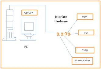
The central processing unit of the system operates as a compact computer responsible for activating the switches that power sensing devices on or off. The configuration of home-based PCs primarily varies in the Distribution Fuse Board (DFB) and the manner in which different household appliances are connected to the central processing unit. Although the central processing unit and the DFB features may be physically connected to the control room, they typically have a backup power source. The layout of the PC-based home appliance control system is illustrated in Figure 1.
The system comprises two main units, as described by Swamy et al. (2002) and Nichols and Myers (2006):
1. Control Unit: This unit utilizes a standard personal computer equipped with Graphical User Interface (GUI) software to manage the electrical appliances.
2. Interface Unit: The interface unit facilitates the connection of high-power loads to the control unit.

1.2. Hardware Design of the Interface Box
The Universal Serial Bus (USB) stands out as one of the most ubiquitous interfaces utilized in a wide array of electronic consumer products today, spanning from PCs, cameras, and GPS devices to MP3 players, modems, printers, and scanners, among others. This interface encompasses data lines, control lines, and status lines. Operating as a high-speed serial interface, USB has the capability to supply power to devices connected to it (Kim et al., 2010; Lin and Brogerg, 2002; Neng-Shiiang et al., 2002).
A USB bus can accommodate up to 127 devices, with connectivity facilitated through a four-wire serial cable ranging from three to five meters in length. Multiple USB devices can be linked to the same bus using hubs, which come in configurations of 4, 8, or even 16 ports. This allows for a hierarchical connection where devices can be plugged into hubs, which in turn can be connected to additional hubs, up to a maximum of six tiers. As per the specification, the maximum distance between a device and its host is approximately thirty meters, achievable by utilizing five hubs. For longer-distance bus communications, alternative methods like Ethernet are recommended.
USB specifications are delineated into two versions: USB 1.1, supporting 11Mbps, and USB 2.0, which can reach speeds of up to 480Mbps. Furthermore, the USB specification defines three data speeds:
– Low speed at 1.5Mb/sec
– Full speed at 12Mb/sec
– High speed at 480Mb/sec.
The maximum power accessible to an external device is capped at around 100mA at 5.0V. USB interfaces typically employ a four-core shielded cable, with two specified types of connectors. These connectors are detailed in Table 1, along with the pin-out information provided in Table 2. Additionally, the specification introduces a mini-B connector, primarily utilized in smaller portable electronic devices such as cameras and handheld devices. While this connector includes a fifth pin named ID, it remains unused. The pin assignment and wire colors for a mini-B connector are also outlined. Notably, two of the pins, Data + and Data -, comprise a twisted pair and serve as differential data signals, alongside some single-ended data states.


