Summary of Basic Microcontroller Use for Measurement and Control
Microcontrollers are central to measurement and control systems in biosystems engineering, enabling data acquisition from sensors and automated actuation. This chapter explains system components (sensors, actuators, microcontroller CPU, memory, I/O, buses, clocks) and signal conversion (A/D, D/A), and outlines microcontroller software tools (IDE, editor, compiler, assembler, debugger, emulator). A simple project demonstrates practical implementation and illustrates how microcontrollers support IoT-enabled remote monitoring and control in applications like weather stations, irrigation, greenhouse, and process control.
Parts used in the Basic Microcontroller Use for Measurement and Control project:
- Microcontroller (with CPU, memory, I/O ports)
- Sensors (e.g., flow rate sensor, temperature sensor, pressure sensor)
- Actuators (e.g., valves)
- Analog-to-digital converter (A/D)
- Digital-to-analog converter (D/A)
- Signal conditioning components (amplifiers, filters)
- Relays or driver interfaces
- Communication interfaces/protocols (UART, USB, I2C, SPI)
- Clock source (quartz crystal oscillator)
- Development tools (PC or laptop with IDE, compiler, assembler, debugger, software emulator)
Introduction
Measurement and control systems play a crucial role in the field of biosystems engineering. In the digital era, these systems are pervasive and essential, serving the dual purpose of gathering data (measurement) and automating processes (control). As an example, consider weather stations that measure variables like temperature, precipitation, wind speed, and other environmental factors. The data collected can be manually analyzed to make informed decisions for tasks like regulating flow rates and pressures for agricultural irrigation, enhancing farm management practices.
Furthermore, measurement and control systems form the fundamental infrastructure for the latest Internet of Things (IoT) technology. In this context, various devices can be monitored and controlled remotely via the internet.
At the heart of these systems lies a critical component, the microcontroller. A foundational understanding of microcontrollers, their mechanisms, and how to leverage them for measurement and control is a prerequisite for all biosystems engineers. This chapter serves as an introduction to these concepts and their practical applications, featuring a straightforward project to illustrate their implementation.
Concepts
Measurement and Control Systems
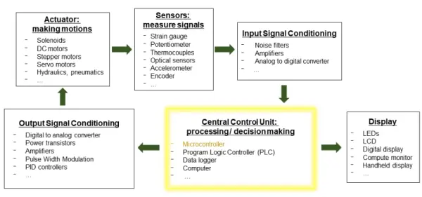
Let’s delve into the intricacies of measurement and control systems. As depicted in Figure 1, these systems involve the generation of signals through mechanical actuators and the subsequent measurement of these signals by sensors, such as the acquisition of a voltage signal from a flow rate sensor. The obtained signal is then directed to a central control unit, often a microcontroller, for comprehensive signal processing, analysis, and decision-making. An illustrative case is assessing whether the flow rate falls within the desired range. Subsequently, the microcontroller issues instructions to control the actuator, such as adjusting the valve opening, while simultaneously presenting the system’s status to users. This process forms an ongoing loop, continuing until interrupted by user intervention or reaching a predefined time limit.
When viewed from the perspective of signals, the signals generated by the actuators and measured by the sensors are typically analog in nature, characterized by their continuous and infinite properties. Often, these analog signals undergo preprocessing steps, including amplification, filtering, or conversion into a discrete and finite digital format to make them suitable for processing by the central control unit. In cases where the actuator exclusively accepts analog signals, the signal generated by the central control unit to manipulate the actuator must be transformed back into an analog format. It becomes evident that the central control unit plays a pivotal role in this intricate process.
The microcontroller assumes a pivotal function within the measurement and control loop, serving as one of the widely adopted central control units. In the subsequent sections of this chapter, our emphasis will be on microcontrollers.
Microcontrollers
A microcontroller, a form of computer, is often overshadowed by the more conspicuous general-purpose computing devices such as desktop computers, laptops, and servers. This less conspicuous but ubiquitous type of computer, the microcontroller, is widely employed in both industry and our daily lives. Microcontrollers are compact computing units, typically housed within a single integrated circuit (IC), featuring limited memory and processing capabilities. They are frequently embedded within larger systems to execute intricate tasks. For instance, a typical automobile can incorporate anywhere from 25 to 40 electronic control units (ECUs), each centered around a microcontroller. Similarly, advanced tractors can boast a similar number of ECUs, with microcontrollers overseeing functions like power distribution, traction, and the management of implements. Microcontrollers are instrumental in environmental control systems for settings like greenhouses and animal enclosures, as well as in process control applications in food processing plants. Each microcontroller within these applications is tasked with specific measurement and control functions, such as monitoring airflow, temperature, internal pressure, or executing higher-level control for a series of microcontrollers.
A fundamental grasp of a microcontroller’s essential components and its operational principles is indispensable for designing effective measurement and control systems.
Primarily, a microcontroller comprises a central processing unit (CPU), memory units, and input/output (I/O) hardware, as illustrated in Figure 2. These components collaborate with one another and interface with external devices through signal pathways known as buses. Each of these components is elaborated upon below.
The CPU, sometimes referred to as a microprocessor, serves as the microcontroller’s core, responsible for primary computations and internal system control. The CPU manages three types of information: data, encompassing digital values for computation or transmission; instructions, specifying data requirements, computational processes, and storage locations for results; and addresses, indicating data or instruction source and destination points. Within the CPU, an arithmetic logic unit (ALU) carries out mathematical operations on data represented as groups of binary digits or “bits,” with each bit holding a value of either 0 or 1. The efficiency of a microcontroller’s CPU is often determined by the number of bits it can process simultaneously, typically 8, 16, or 32 bits.
Memory units, commonly known as memory, are responsible for storing data, addresses, and instructions that the CPU accesses during processing. There are generally three types of memory: random-access memory (RAM), a volatile memory used for storing data and currently executed programs; read-only memory (ROM), which provides permanent storage for system instructions even when the microcontroller is powered down; and erasable-programmable read-only memory (EPROM), a semi-permanent memory capable of storing instructions that may require occasional changes, such as those governing the specific functions of the microcontroller. Firmware, a program typically permanently stored in ROM or EPROM, controls the hardware and establishes a standardized operating environment for more complex software developed by users. Firmware remains unaltered unless system updates are necessary to rectify issues or introduce new features. While EPROMs were initially erased using ultraviolet light, flash memory (electrically erasable programmable read-only memory or EEPROM) has become the prevailing norm. The quantity of RAM, expressed in bytes, kilobytes, megabytes, or gigabytes, influences operational speed, data processing capacity, and the complexity of programs that can be executed.
Digital input and output (I/O) ports establish connections between the microcontroller and external devices through digital signals. These signals rely on voltage distinctions to signify on and off states, with each digital port configurable as either an input or an output. Input ports retrieve the status of external devices, while output ports issue control commands to external devices. Most microcontrollers operate within a voltage range of 0 to +5V and manage limited current, as the voltage signal is not directly utilized; instead, the binary status is of significance. When voltage and current must be used directly to drive a device, an intermediary component like a relay or voltage digital analog converter is required between the port and the device. Typically, digital I/O ports communicate with external devices using established communication protocols, including serial communication protocols such as UART (universal asynchronous receiver-transmitter), USB (universal serial bus), I2C (inter-integrated circuit), and SPI (serial peripheral interface).
Analog input and output (analog I/O) ports are directly connectable to the microcontroller. These ports are essential for interfacing with devices that produce analog signals (e.g., temperature, pressure, strain, rotation) and for actuating devices that necessitate analog signals. Analog ports are equipped with either analog-to-digital (A/D) converters or digital-to-analog (D/A) converters.
To facilitate communication and data exchange between the CPU, memory, and I/O ports, electrical conductors, termed buses, serve as the central nervous system of the computer. These buses enable data, addresses, and control signals to be shared among all system components and are controlled by specific bus controllers. Three primary types of buses include the data bus, responsible for data transfer to and from data registers in various system components; the address bus, which manages memory addresses; and the control bus, regulating various system control functions.
The address bus is responsible for conveying the location of a system component that the CPU intends to interact with, or it specifies a particular data storage location within the memory that the CPU wishes to access. On the other hand, the control bus serves as the conduit for transmitting operational signals between the CPU and various system components. These signals include read and write commands, the system clock signal, and system interrupts.
In addition, clock, counter, and timer signals play a crucial role in synchronizing activities among different components within a microcontroller. Typically, a clock signal consists of a sequence of pulses with a constant and known frequency, generated by a quartz crystal oscillator. For instance, a CPU clock represents a high-frequency pulse signal employed to time and coordinate diverse tasks within the CPU. A system clock, on the other hand, is used to synchronize multiple system operations, including data input and output, sampling, and A/D and D/A processes.
Microcontroller Software and Programming
To program and simulate microcontroller code on a PC or laptop, most programming errors can be identified and rectified during the simulation process. An Integrated Development Environment (IDE) typically encompasses the following components:
– An editor, which facilitates microcontroller programming using a relevant high-level programming language such as C, C++, BASIC, or Python.
– A compiler, responsible for translating the high-level language program into low-level assembly language specific to a particular microcontroller.
– An assembler, tasked with converting the assembly language into machine code, expressed in binary format (0s and 1s).
– A debugger, serving to error-check (also referred to as “debug”) the code and test whether it performs its intended functions. The debugger is primarily adept at identifying syntax errors, which encompass statements that are unintelligible and uncompileable, as well as redundant code, which comprises lines in the program that serve no purpose. The debugger provides information about the error’s line number or location to aid in resolving issues. Additionally, programmers can integrate error-testing components when crafting code to utilize the debugger in confirming that the program aligns with its initial objectives.
– A software emulator, which enables program testing on the PC or laptop before conducting hardware testing.
It’s worth noting that while not all of these components may be directly presented to the user within an IDE, they are inherently part of the IDE’s functionality. For certain system development projects, a hardware emulator may also be accessible, consisting of a printed circuit board connected to the PC or laptop via a ribbon cable that links to I/O ports. This emulator allows for loading and running programs to perform testing before the microcontroller is integrated into a functional measurement or control system.
Source: Basic Microcontroller Use for Measurement and Control
- What role does a microcontroller play in measurement and control systems?
The microcontroller serves as the central control unit for signal processing, analysis, decision making, and issuing control commands to actuators. - How are analog sensor signals handled by the microcontroller?
Analog signals are often preprocessed (amplified, filtered) and converted to digital format via A/D converters for processing by the microcontroller. - Can microcontrollers directly drive high-voltage or high-current devices?
No; when voltage and current must be used directly to drive a device, an intermediary component like a relay or driver is required between the port and the device. - What types of memory are found in a microcontroller?
Common memory types include RAM for volatile data and programs, ROM for permanent storage, and EPROM/EEPROM/flash for semi-permanent or updateable firmware. - Which communication protocols are commonly used with microcontroller I/O ports?
Serial protocols such as UART, USB, I2C, and SPI are commonly used for communication with external devices. - What components are included in a typical IDE for microcontroller development?
An IDE typically includes an editor, compiler, assembler, debugger, and a software emulator for testing code. - How do buses function within a microcontroller?
Buses (data, address, control) facilitate communication of data, memory addresses, and control signals among the CPU, memory, and I/O ports. - Why are clock, counter, and timer signals important?
They synchronize activities among components, timing operations like CPU tasks, data sampling, and A/D and D/A processes. - What is firmware in a microcontroller?
Firmware is a program stored in ROM or EPROM that controls hardware and provides a standardized operating environment for user software. - Can microcontroller code be tested before hardware deployment?
Yes; code can be simulated and debugged using a software emulator and IDE, and hardware emulators can test programs before integration.