
Summary of Digital Voltmeter Using PIC Microcontroller 16F877A and Seven Segments Display (0-30V)
This article describes building a PIC16F877A-based digital panel voltmeter (0–30V DC) with eight seven-segment displays. It uses the PIC’s ADC to measure voltage via a resistor voltage divider, requires MikroC-compiled firmware (HEX provided), and employs common components like transistors for driving displays and a 20 MHz crystal.
Parts used in the Digital Voltmeter Using PIC Microcontroller 16F877A and Seven Segments Display (0-30V):
- PIC16F877A Microcontroller
- Transistor BC548 x4
- Resistor 1KΩ x5
- Resistor 10KΩ
- Resistor 100KΩ
- Resistor 22KΩ
- Seven segment display x8
- Crystal 20MHz
- Capacitor 10µF
- Capacitor 33pF x2
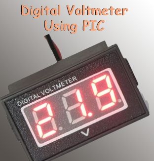
We are all aware of about voltmeters (voltage meter), which is nothing but a device used to measure voltage between given two terminals. Apart from the basic usage digital voltmeters are also employed as panel meters for automation systems and robotics. There are analog and Digital voltmeters are available in the market. Have you ever thought about building a PIC microcontroller based digital voltmeter with seven segment display output? Here I’m explaining the constructional details of digital panel voltmeter using PIC16F877A microcontroller. It can measure voltage between 0V to 30V DC. Seven segment units are provided for digital voltmeter display which gives clear visibility of digits from long distance comparing to LCD display.
The program for digital voltmeter using pic microcontrolle is compiled using Mikro C. We are providing the .HEX file for this simple voltmeter absolutely free!
 Circuit Schematics of Digital Voltmeter Using PIC Microcontroller
The following figure shows digital voltmeter panel circuit diagram with microchip PIC.
Components Required for Digital Voltmeter Using PIC Microcontroller
- PIC16F877A Microcontroller
- Transistor (BC548 x4)
- Resistor (1KΩ x 5; 10KΩ; 100KΩ; 22KΩ)
- Seven segment Display x8
- Crystal (20MHz)
- Capacitor (10µF, 33PF x2)
Working of Digital Voltmeter Using PIC Microcontroller
- PIC programming is quite easy if you have a perfect C compiler like Mikro C pro, MPLAB Hi-tech C etc.
- If you are new to PIC microcontroller I recommend to checkout our previous articles and Getting started guides for PIC MCU. You may also checkout our PIC Projects
- PIC16F877A has inbuilt ADC (Analog to Digital Converter) Module, I used ADC to read input voltage value.
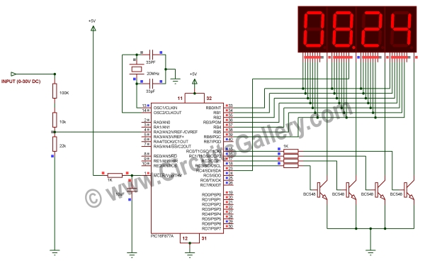 Measuring Voltage and Design of Voltage Divider Circuit
- First of all let I discuss how do we measure voltage? Actually PIC’s ADC can measure 0V to +5V, but here our voltage range is 0V to +30V.
- Hence we can’t feed the input voltage directly to the controller’s ADC pins. Instead of feeding directly, input voltage is reduced by a combination of voltage divider resistors.
For more detail: Digital Voltmeter Using PIC Microcontroller 16F877A and Seven Segments Display (0-30V)
- What voltage range can this voltmeter measure?
It can measure 0V to 30V DC. - Which microcontroller is used in the project?
The project uses the PIC16F877A microcontroller. - How is a voltage above 5V measured by the PIC ADC?
By using a resistor voltage divider to reduce input voltage into the ADC 0–5V range. - What display type is used for the voltmeter output?
Eight seven segment displays are used for digital output. - Which compiler was used to create the program for the PIC?
The program is compiled using Mikro C (MikroC pro). - Is the compiled firmware provided?
The article states the HEX file for the voltmeter is provided free. - Does the PIC16F877A have an ADC module?
Yes, PIC16F877A has a built-in ADC module used to read the input voltage. - What frequency crystal is used?
A 20MHz crystal is used in the circuit.
