PICDEM FS USB Mass Storage Device using PIC18F4550 with Proteus Simulation

Summary of PICDEM FS USB Mass Storage Device using PIC18F4550 with Proteus Simulation


This article details a Proteus simulation project emulating a USB Mass Storage Device using the PIC18F4550 microcontroller. It demonstrates USB communication logic, SPI-based storage interfacing, and real-time host interaction without physical hardware. Ideal for students and engineers, the system mimics a flash drive to teach embedded firmware development and USB protocols through safe, controlled testing.

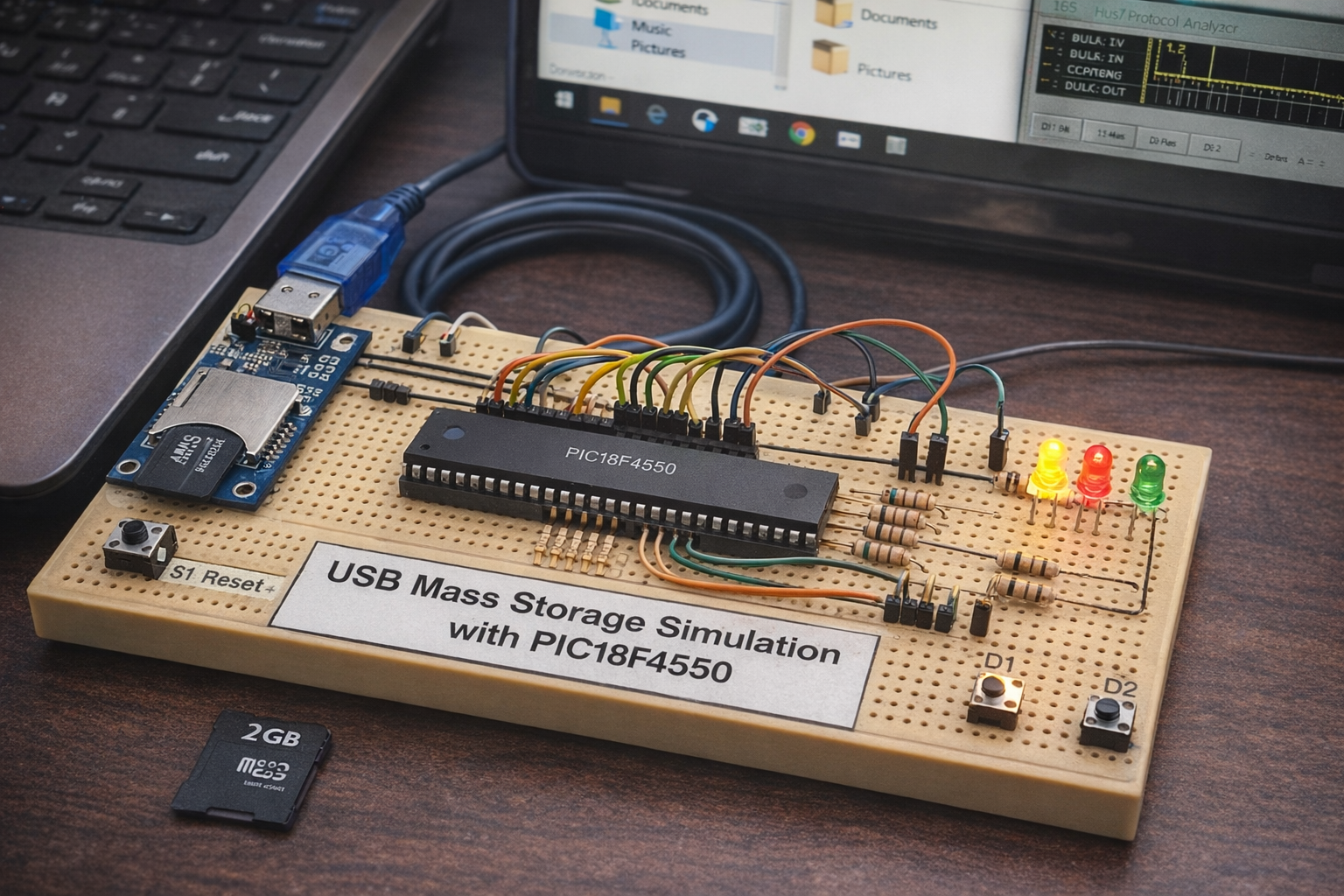
Parts used in thePICDEM FS USB Mass Storage Device:

  • PIC18F4550 Microcontroller
  • USB Connector (Virtual USB in Proteus)
  • MMMC/SD Card Module
  • Resistors (pull-ups and current limiting)
  • LEDs (D1, D2, D3, D4)
  • Push Buttons (Reset, control switches)
  • Power supply and ground connections

Introduction

This microcontroller project demonstrates how to simulate a USB Mass Storage Device (MSD) using the PIC18F4550 in a Proteus simulation environment. The system mimics how a USB flash drive communicates with a computer, making it highly valuable for learning embedded systems and USB protocol basics.

It is especially useful for students and engineers exploring DIY electronics, firmware development, and USB interfacing without needing physical hardware. By using Proteus VSM, the project allows safe testing of USB communication logic in a controlled environment.

This project bridges the gap between theory and practice by simulating real-world USB device behavior.

PIC18F4550 USB mass storage prototype setup
Illustrative View of the Concept.

How the Project Works (Overview)

The system uses the PIC18F4550 microcontroller, which has built-in USB functionality, to emulate a USB Mass Storage Device.

When the simulation runs:

  • The microcontroller initializes its USB module
  • It communicates with the host (PC) via USB connector
  • The firmware handles USB requests and behaves like a storage device
  • External memory (MMC/SD card interface) is used to simulate storage
  • LEDs indicate device activity and status

The host system detects the device as a removable drive, enabling basic read/write operations in the simulated environment.

Workflow Explanation

Based on the schematic:

  1. USB Interface Block
    • USB connector provides communication between PC and microcontroller
    • D+ and D− lines are connected to PIC18F4550 USB pins
  2. Microcontroller Core (PIC18F4550)
    • Handles USB protocol stack
    • Manages data transfer between USB and storage interface
    • Controls LEDs and user inputs
  3. Storage Interface (MMC/SD Module)
    • Connected via SPI communication (CS, DI, DO, CLK)
    • Acts as external storage medium
  4. User Input Section
    • Reset switch and control buttons (CD, WD, S1)
    • Used for control and testing functionality
  5. Status Indicators
    • LEDs (D1–D4) display activity such as data transfer or system status

Key Features

  • USB Mass Storage Device (MSD) simulation
  • Built-in USB support using PIC18F4550
  • SPI-based MMC/SD card interface
  • Real-time interaction with host system in Proteus
  • LED indicators for system status and debugging
  • Supports USB read/write request handling
  • No physical hardware required (fully simulated)

Components Used

  • PIC18F4550 Microcontroller
  • USB Connector (Virtual USB in Proteus)
  • MMC/SD Card Module
  • Resistors (pull-ups and current limiting)
  • LEDs (D1, D2, D3, D4)
  • Push Buttons (Reset, control switches)
  • Power supply and ground connections

Applications

  • Learning USB protocol in embedded systems
  • Developing firmware for USB devices
  • Educational demonstration of mass storage devices
  • Testing embedded USB designs before hardware implementation
  • Prototyping USB-based data logging systems

Add Your Heading Text Here

The firmware (not shown but inferred from design) typically includes:

  • USB Stack Initialization
    • Configures the PIC18F4550 USB module
    • Sets device descriptors for mass storage class
  • SPI Communication Module
    • Interfaces with MMC/SD card
    • Handles read/write sector operations
  • USB Request Handling
    • Processes commands from host (read/write requests)
    • Transfers data between host and storage
  • I/O Control
    • Manages LED indicators
    • Reads input switches
  • Main Loop
    • Continuously monitors USB state
    • Handles data transactions   

Proteus Simulation

In Proteus, the simulation replicates how a real USB flash device works:

  • When the simulation starts, the system initializes USB communication
  • The virtual PC detects a USB Mass Storage Device
  • The device appears like a removable drive
  • Data transactions are visible via USB analyzer
  • LEDs blink based on activity

Conclusion

This project is a solid introduction to USB-based microcontroller projects using Proteus simulation. It demonstrates how embedded systems can emulate real-world devices like USB drives, making it an excellent learning tool for both beginners and advanced users.

By combining USB communication, SPI storage, and firmware control, this project provides hands-on experience in practical electronics and embedded systems design.

Quick Solutions to Questions related toPICDEM FS USB Mass Storage Device:

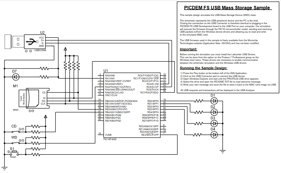
  • How does the system emulate a USB flash drive?
    The system uses the PIC18F4550 microcontroller with built-in USB functionality to initialize its USB module and communicate with the host PC via a USB connector.
  • What role does the MMC/SD card play in this project?
    The MMC/SD card acts as an external storage medium connected via SPI communication to simulate data storage for the device.
  • Can this project be tested without physical hardware?
    Yes, the project is fully simulated in Proteus VSM, allowing safe testing of USB communication logic without needing physical components.
  • How are status and activity indicated during operation?
    LEDs (D1–D4) display activity such as data transfer or system status based on user inputs and USB transactions.
  • Does the firmware handle read and write requests?
    Yes, the firmware processes commands from the host to handle USB read/write requests and transfers data between the host and storage.
  • What interface is used to connect the storage module?
    The storage interface connects to the microcontroller via SPI communication using CS, DI, DO, and CLK lines.
  • What is the primary educational value of this project?
    It bridges theory and practice by simulating real-world USB device behavior, making it valuable for learning embedded systems and USB protocol basics.

About The Author

Ibrar Ayyub

I am an experienced technical writer holding a Master's degree in computer science from BZU Multan, Pakistan University. With a background spanning various industries, particularly in home automation and engineering, I have honed my skills in crafting clear and concise content. Proficient in leveraging infographics and diagrams, I strive to simplify complex concepts for readers. My strength lies in thorough research and presenting information in a structured and logical format.

Follow Us:
LinkedinTwitter