DHT22 Low Cost Humidity Sensor using PIC18F25K20 with Proteus Simulation

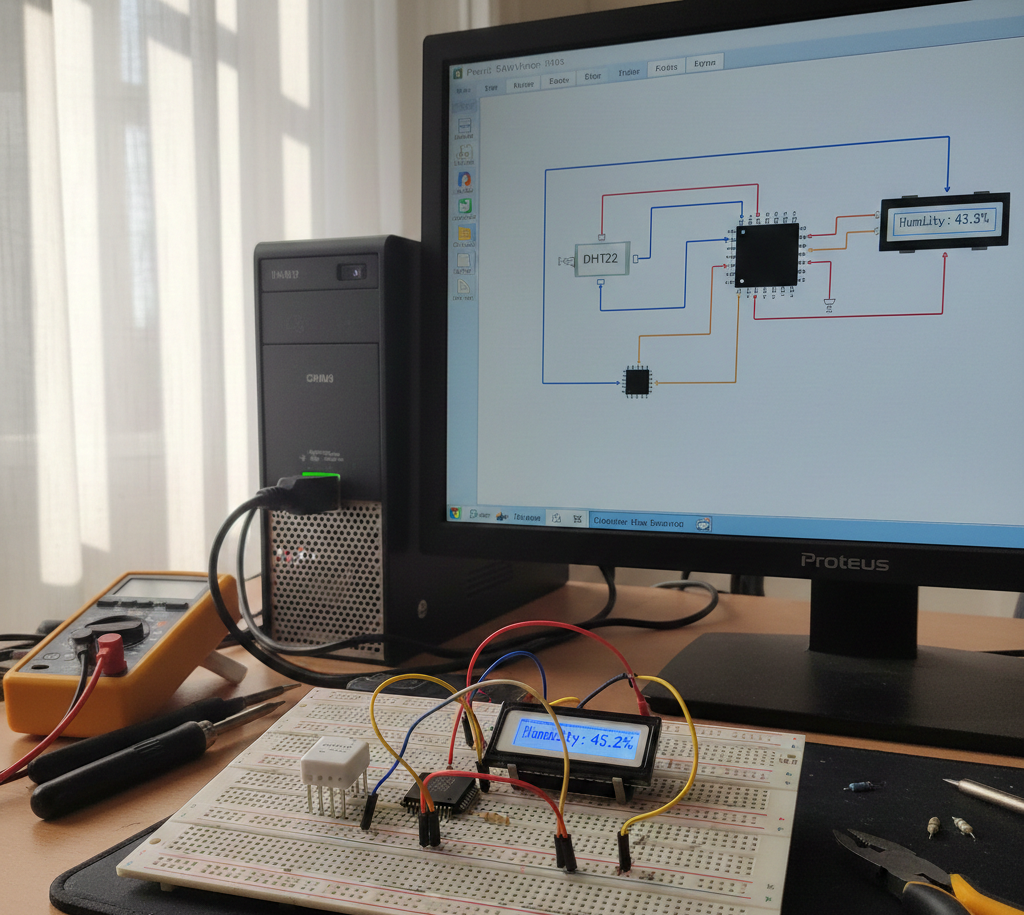
Summary of DHT22 Low Cost Humidity Sensor using PIC18F25K20 with Proteus Simulation


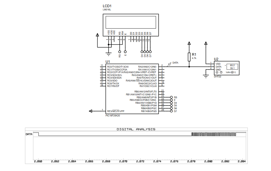
This project shows interfacing a DHT22 (RHT03) temperature and humidity sensor with a PIC18F25K20 in Proteus, reading 40-bit timed data via a single-wire protocol on RA0, decoding via Timer2 pulse-width measurement, validating with checksum, and displaying results on a 16×2 LCD using XC8 firmware and the PIC internal 4 MHz oscillator.

Parts used in the DHT22 Low Cost Humidity Sensor using PIC18F25K20 with Proteus Simulation:

  • PIC18F25K20 microcontroller
  • DHT22 (RHT03) temperature & humidity sensor
  • 16×2 character LCD (LM016L)
  • 4.7kΩ pull-up resistor
  • 5V power supply
  • Proteus simulation environment

Introduction

This microcontroller project demonstrates how to interface a DHT22 (RHT03) digital temperature and humidity sensor with a PIC18F25K20 using Proteus simulation.
The project reads real-time temperature and relative humidity data and displays it on a 16×2 LCD.
It’s a practical example of embedded systems communication, timing-critical digital sensors, and LCD interfacing.
Designed for learners and hobbyists, this setup is ideal for understanding single-wire sensor protocols in DIY electronics.
The complete firmware is written in MPLAB XC8, making it easy to compile and modify.

DHT22 humidity monitoring prototype
Illustrative View of the Concept.

How the Project Works (Overview)

The PIC18F25K20 communicates with the DHT22 sensor over a single data line connected to RA0.
The microcontroller sends a start signal, waits for the sensor response, and then reads 40 bits of data containing humidity, temperature, and checksum values.
A timer-based approach is used to measure pulse widths, which determines whether each received bit is a logical ‘0’ or ‘1’.
Valid sensor data is processed and displayed on a 16×2 LCD in human-readable form.

Block Diagram / Workflow Explanation

  1. PIC18F25K20 initializes internal oscillator and I/O pins

  2. Start signal sent to DHT22 via RA0

  3. DHT22 responds with timing-encoded digital data

  4. Timer2 measures pulse width for each bit

  5. 40-bit data frame decoded (Humidity, Temperature, Checksum)

  6. Checksum verified to ensure data integrity

  7. LCD displays temperature and humidity values

Key Features

  • Digital temperature and humidity measurement using DHT22

  • Single-wire sensor communication protocol

  • Timer-based pulse width detection

  • Real-time LCD data display

  • Checksum validation for reliable readings

  • Fully simulated in Proteus VSM

  • Uses internal oscillator (no external crystal required)

Components Used

  • PIC18F25K20 microcontroller

  • DHT22 (RHT03) temperature & humidity sensor

  • 16×2 character LCD (LM016L)

  • 4.7kΩ pull-up resistor

  • Power supply (5V)

  • Proteus simulation environment

Applications

  • Weather monitoring systems

  • Indoor climate monitoring

  • Smart home sensor nodes

  • Agricultural humidity tracking

  • Educational embedded systems labs

  • IoT sensor prototyping (with extensions)

Explanation of the Code (High-Level)

  • Initialization section configures oscillator, I/O pins, interrupts, and Timer2

  • Start signal function triggers communication with the DHT22

  • Response check routine confirms sensor presence

  • Byte reading function decodes each bit using pulse width timing

  • Interrupt service routine handles timeout conditions

  • Main loop continuously reads sensor data and updates the LCD

  • Checksum logic ensures data accuracy before display

Source Code

Download
#include 
#include 
#include "lcd.h"

#define _XTAL_FREQ   4E6

#pragma config IESO = OFF, FOSC = INTIO67, FCMEN = OFF
#pragma config BOREN = OFF, PWRT = OFF
#pragma config WDTEN = OFF
#pragma config CCP2MX = PORTC, PBADEN = OFF, MCLRE = ON
#pragma config DEBUG = OFF, STVREN = ON, XINST = OFF, LVP = OFF

Proteus Simulation

In Proteus VSM, the PIC18F25K20 executes the XC8 firmware while the DHT22 model generates digital pulse sequences.
The logic analyzer confirms correct timing behavior, and the LCD updates in real time with temperature and humidity values.
This allows complete verification without physical hardware.

(FAQs)

1. Why does the DHT22 need precise timing?

Because data bits are encoded using pulse width, accurate timers are essential.

2. Can this project run on other PIC18 devices?

Yes, with minor pin and configuration changes.

3. Why is Timer2 used instead of delays?

Timer-based measurement ensures accurate bit detection.

4. What causes checksum errors in Proteus?

Incorrect timing, missing pull-up resistor, or wrong clock frequency.

5. Can I replace DHT22 with DHT11?

Yes, but data format and resolution will differ.

6. Is external crystal required?

No, the internal 4 MHz oscillator is sufficient.

7. Can this project be extended for IoT?

Yes, by adding UART, Wi-Fi, or GSM modules.

Conclusion

This project is a clean, real-world example of sensor interfacing, timing-critical communication, and LCD control using a PIC microcontroller.
It’s perfect for anyone learning embedded systems through Proteus simulation and practical electronics.
By studying and modifying this design, you gain hands-on experience with firmware timing, digital sensors, and reliable data handling.

Quick Solutions to Questions related to DHT22 Low Cost Humidity Sensor using PIC18F25K20 with Proteus Simulation:

  • Why does the DHT22 need precise timing?
    Because data bits are encoded using pulse width, accurate timers are essential.
  • Can this project run on other PIC18 devices?
    Yes, with minor pin and configuration changes.
  • Why is Timer2 used instead of delays?
    Timer-based measurement ensures accurate bit detection.
  • What causes checksum errors in Proteus?
    Incorrect timing, missing pull-up resistor, or wrong clock frequency.
  • Can I replace DHT22 with DHT11?
    Yes, but data format and resolution will differ.
  • Is external crystal required?
    No, the internal 4 MHz oscillator is sufficient.
  • Can this project be extended for IoT?
    Yes, by adding UART, Wi-Fi, or GSM modules.
  • Where is the sensor data displayed?
    On a 16×2 LCD in human-readable form.

About The Author

Ibrar Ayyub

I am an experienced technical writer holding a Master's degree in computer science from BZU Multan, Pakistan University. With a background spanning various industries, particularly in home automation and engineering, I have honed my skills in crafting clear and concise content. Proficient in leveraging infographics and diagrams, I strive to simplify complex concepts for readers. My strength lies in thorough research and presenting information in a structured and logical format.

Follow Us:
LinkedinTwitter