Summary of LED Cube with SnakeGo
Summary: An 8x8x8 LED cube driven by a PIC32 displays 3D patterns and runs a 3D Snake game controlled by an NES controller. The design uses persistence of vision with 8 layers and 64 columns, multiplexed via 8 latches, two 3-to-8 decoders, and a Darlington sink driver to reduce I/O to 14 pins. Software handles cube refreshing via ISR, a Snake protothread, NES polling, and multiple lighting effects including opening text and game-over shows.
Parts used in the LED Cube with SnakeGo:
- PIC32MX microcontroller
- 512 single-color LEDs (8x8x8 cube)
- 74HC238 3-to-8 decoder (two units)
- 74HC574N 8-bit latch (eight units)
- ULN2803 Darlington sink driver
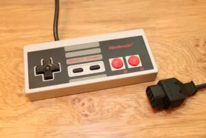
- NES controller (serial-in parallel-out shift register controller)
- Supporting wiring, soldered PCB or perfboard, and power supply
Introduction
The idea of our final project is to design and implement a PIC32-drived 8x8x8 LED cube with 3-dimensional display. Besides 3D display feature, another major feature of this magical LED cube is that it provides a playing field and users can play 3D snake game on the cube by using NES controller. Six buttons on the NES controller are designed to change the moving direction (forward, backward, up, down, left, right) of the snake. One button is designed for user to change game mode anytime during game in order to adjust the snake moving speed (default mode for normal speed; easy mode for slower speed; hard mode for faster speed). Another button is designed to restart the game. Before game starts, 3D “SNAKE GO” characters are showed as game opening show, and each time after game ends random 3D light effects are showed. Overall, this LED cube is really a great product to help people get relaxed and kill time in their spare time.
High Level Design
Overview
Our project LED cube is similar to a LED screen, but the special aspect is that the LED cube has the ability to display patterns in third dimensions, which is the same as most of the objects in real life. The LED cube lighting patterns can be controlled by PIC32 microcontroller unit based on the program loaded into it.
Block Diagram
LEDs and Display Diagram Control
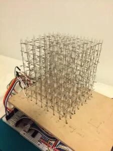
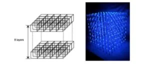
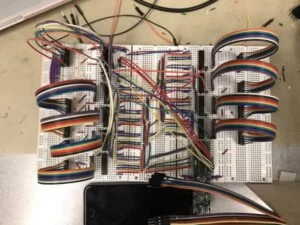
An 8x8x8 LED cube is made up with 512 LEDs. The easiest way to control the cube is that each I/O port controls one LED. But obviously it is not impossible to control each LED with one I/O port of PIC32 microcontroller. As a result, our design is mainly focused on using less I/O pins to control 512 LEDs. Instead, we could take the advantage of persistence of vision, which is an optical illusion. Which means if a led flashes at a high frequency, the image still stay on retina for a while after the LED turns off, and this give us an illusion that the LED is lit all the time. In turns, if each layer of the cube is lit one after another in a high frequency, there will be an illusion of a 3-dimentional image.
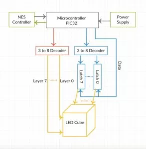
With the above setup, we only need to control 64 anodes and 8 cathodes to control all the LEDs. In our design, the LED cube built up with 8 LED layers, and 64 columns. All the cathode legs of each LED in a layer are connected together, and all the anode legs in the same column are connected together. Consequently, each of the 8 layers and each of the 64 columns can be controlled individually. Because of the limited number of I/O pins of PIC 32, we designed to use 8 latches combined with a 3 to 8 decoder to control the 64 columns, and another 3 to 8 decoder to select which layer should be lit, as shown in the block diagram above. In this design, we only use 8(data for latches) + 3(decoder for latch selection) + 3(decoder for layer selection) = 14 I/O pins to control 512 LEDs, and make them display 3D patterns. More detailed implementation is illustrated in hardware implementation section.
Snake Game Control through NES Controller
The NES controlled we used for this project simply consists with an 8-bit parallel-in-serial-out shift register, so only three I/O pin need to be used to control the snake. One is used for receiving the output data from the controller. One is used to output a clock to the controller, and another pin is used to generate pulse for latch line to grab data.
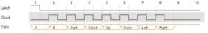
Steps to grab data from NES controller to PIC 32 (as the waveform shown below):
1. Pulse the LATCH line so that the shift register can grab the data.
2. Read the DATA pin and save this button state.
3. Pulse the CLOCK line and save this button state.
4. Repeat last step six more times.
5. Do something with all of this data.
More detailed implementation is illustrated in hardware and software implementation sections.
Hardware/Software Tradeoffs
There were several tradeoffs for the hardware and software part used in the project.
For hardware, we initially planed to use RGB LEDs for the cube, which can ensure colorful and the polychrome lighting effects are much better than the effects of LEDs with only one color. However, due to the limited I/O pins, we had to use the common LEDs with an anode and a cathode for the LED cube. And in order to used less I/O pins, we decided to light every layer one after another and at a very high frequency.
For software, we firstly considered using UART serial cable and PuTTY for the communication between running program and the PC and control the moving direction in snake game. However, when typing commands, the user has to hit enter button every time, which is inconvenient and tedious operation for playing a game. As a result, we used the NES controller instead to improve the user experience.
Hardware Design
The LED cube contains 8 horizontal layers and 64 columns. The cathodes of all the LEDs in each single horizontal layer are soldered together, and the anodes are soldered in each column.
Each horizontal layer and column should be controlled separately. Theoretically, 72 (64 anode columns plus 8 cathode layers) I/O ports are needed to control the entire cube. However, this is not practical because PIC32MX only provides 19 general I/O ports that are able to use. Thus, we build a multiplexer circuit to compress the number of I/O ports needed to 14. The details of the circuit are provided below.
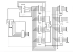
The circuit consists of a PIC32MX microcontroller, 8 latches, 2 3-to-8 decoders and a Darlington sink driver.
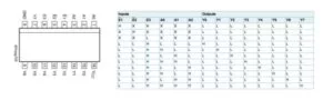
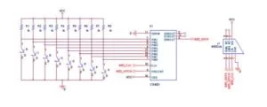
1. 3-to-8 Decoder (74HC238)
74HCT238 is a 3-to-8 line decoder, which decodes three binary weighted address inputs (A0, A1 and A2) to eight active high mutually exclusive outputs (Y0 to Y7). The function of 74HC238 is to select horizontal layer and latch. The LED cube relies on the persistence of vision by flashing each layer really fast. Actually, we select a single layer at each clock cycle. So, one of the 3-to-8 decoder is to select the layer. After the layer is selected, the cube is flashed row by row, where a latch controls each row. So, the other decoder is to select which latch should output the pattern to the LED cube. The schematic and function table of 74HC238 is shown below.
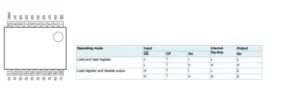
2. Latch (74HC574N)
74HCT574 is an 8-bit positive-edge triggered D-type flip-flop with 3-state outputs. The device features 8 inputs (D0-7), 8 outputs (Q0-7), a clock (CP), and an output enable (OE) inputs. The function of 74HC574 is to hold 8-bit input data and then output the 8-bit information data when CP encounters a positive edge. Once the input data is latched to the outputs, it will stay regardless of any changes until new input data is loaded and CP is pulled high again. The 8-bit input data is the pattern going to be display on a row of LED cube, so the output ports (Q0-7) are connected to the lead of anode columns in each row.
4. Darlington Sink Driver (ULN2803)
ULN2803 is the commonly used driver IC. It is a high voltage, high current Darlington transistor array ideally suited for interfacing low logic level digital circuits and high voltage/current circuits. The connection of ULN2803 IC is to control activations of cathodes of 8 horizonta layers of the LED cube.
Software
The software development is even more challenging than the hardware part. With many different aspects to consider, inter-conflicts to avoid, it took us a quite some time to get everything working in harmony.
Here is an outline of our software development, it is also the order in which we developed the software part.
1. Cube Refreshing
2. 3D Snake
3. NES Controller
4. Lighting Effects
Cube Refreshing
We are using a 2D array unsigned char cube[8][8] to store the status of the 512 LEDs. The unsigned char has 8bits, which makes the 3rd dimension. Each bit represents a led, 0 means off and 1 means on. We could have used 3D array to store the status, but it would be so space-inefficient.
We set a constant refreshing rate to move the data on the 2D array to the actual on-off of the LEDs. So, the only thing we need to concern to change what the cube looks like is to alter the data of the 2D array, and then the refreshing will do the rest to make it real.
Without any doubt, the best way to implement refreshing is using the ISR. Timer 2 is set up with a prescaler of 1_1. When the timer comes to 20000, the ISR is triggered. Since the system frequency is 40MHz, the frequency of ISR is 40M/20000 = 2kHz.
Each time ISR is triggered, the followings are done in the order the are present:
1. The 8 output data pins of the PIC are set to 0
2. The 8 latches are enabled one by one to synchronize their output with input
3. One layer is enabled according to the variable current_layer
4. Load data to latch 0, enable it
5. Load data to latch 1, enable it
6. Load data to latch 3, enable it
7. Load data to latch 2, enable it
8. Load data to latch 6, enable it
9. Load data to latch 7, enable it
10. Load data to latch 5, enable it
11. Load data to latch 4, enable it
12. Increase variable current_layer to reference the next layer
As you can tell, each ISR refreshes one layer, so 8 ISR refreshes the whole cube. The refreshing rate of the cube turns out to be 2kHz/8= 250Hz, which is high enough that your eyes cannot tell they are flashing. This is how we make create stable display on the cube.
3D Snake
A protothread named Snake Thread is implemented to conduct the 3D snake game. We create structure Snake which consists of the x-y-z coordinate and the heading to represent a node of snake body. An array Snake[] is to store the whole snake.
We use another 2D array unsigned char fb[8][8] which is identical to the unsigned char cube[8][8] to store the progress of the snake game, and copy fb[][] to cube[][] at a changeable rate, speed (which is 500ms by default), so that the game is refreshed every ,say, 500ms. We also make advantage of this variable to alter the speed of the snake game to introduce more variations to the game. We implemented three speeds, slow, medium and fast, which is changed when pressing the button on the NES controller.
We have several functions working to implement the 3D snake:
• void initial();
• void show();
• void create_food();
• void button();
• void move();
• void check_crash();
• void check_head(int x, int y, int z);
void initial();
This function is placed in the beginning of Snake Thread. It does the initialization work including generating a random coordinate for the head of the snake, storing in Snake[], and calling the create food function.
void create_food();
This function creates a food dot in a random position for the snake to pick up.
void show();
This function is actually the body of the Snake Thread. It checks the current status of the game and, if the game is not over, copy the fb[][] to cube[][] to display the game on the cube.
This function changes the direction in which the snake is heading for accoding to the variable key.
void move();
This function moves the snake to the next position and call the two checking functions below.
void check_crash();
This function sets the gameOver flag to 1 if the snake hits the walls or hits itself.
void check_head(int x, int y, int z);
This function checks what the head hits after moving. If it’s a food, eat it and update the body; if it’s vacant, move the whole body forward.
NES Controller
At first, we were considering using the UART communication between PIC and PC, and use the input of the PC keyboard to control the snake. However, it turns out so inconvenient, because you have to press enter every time you want to give a command. So, we move to a more player-friendly method to control the snake— the NES controller. We build another protothread to keep polling for the input of the NES controller.
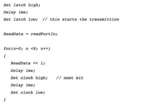
The NES controller is a serial communication device, which uses only 3 ports of the PIC, data-in, clock and latch. The typical waveform is shown in Figure 3.
We use the left four buttons to move to left, right, forward, backward on a plane, and the right two buttons to move upwards and downward. This makes a 6-direction 3D control. The option button on the NES control is assigned to change the speed of the game while the start button is assigned to restart the game. This thread seems very simple and straightforward, however we had a difficult time implementing this thread, for it easily conflicts with other features. We had to make compromise to reconcile this with other features in this project.
The Control Thread implements pseudo code like this to keep polling for the input.
Lighting Effects
To maximize the charm of the LED cube, we added some splendid lighting effects to our project. These effects have a marvelous visual impact on the audience.
We implement two set of lighting effects to the game, opening effects and the effects triggered when game is over (your snake hits the walls or itself). The opening effects display our project name “SNAKE GO” on the cube. The letters fly through the cube one by one and end with a big smiling face. When the game is over, if the reset button is not pressed, random effects take place on the cube, like conducting a lighting show. It is surprisingly catching to watch the cube performing the lighting show when you turn off the lights
We first start with very fundamental functions like setting/clearing a voxel in the cube[][], then we go with functions to light up a plane, a line, a box and something like those. We refer these as low-level functions, and then we can continue with more complex ones based on what we already have. Finally, we have totally 12 effects working.
Results
We had created a fully functional 8x8x8 LED cube. The cube successfully displays the game opening 3D patterns. Users are able to play 3D snake game on this LED cube by NES controller to change snake’s moving direction (up, down, left, right, forward, backward), to change game mode, and to restart the game after snake death. Random 3D light effects are successfully displayed continuously after the death of snake, until the user choose the restart the game. Video demonstrations are shown below.
Source: LED Cube with SnakeGo
- How many LEDs are in the cube?
The cube contains 512 LEDs arranged as an 8x8x8 structure. - How does the design reduce the number of PIC32 I/O pins needed?
It uses persistence of vision with 8 layer cathodes and 64 column anodes, controlled via eight 8-bit latches and two 3-to-8 decoders to compress I/O to 14 pins. - Which IC selects the active layer and which latch to enable?
The 74HC238 3-to-8 decoders are used to select the horizontal layer and to select which latch to enable. - What component holds and outputs the 8-bit row pattern?
The 74HC574N 8-bit latches hold input data and output the 8-bit pattern to the anode columns. - How are the cathodes for each layer driven?
The ULN2803 Darlington sink driver controls activation of the eight horizontal layer cathodes. - How many PIC32 pins are used to interface with the NES controller?
The NES controller uses three PIC32 pins: data-in, clock, and latch. - How is the cube refreshed to create a stable 3D image?
A Timer 2 ISR triggers at 2 kHz, refreshing one layer per ISR so the full cube refreshes at 250 Hz using the cube[8][8] buffer. - How many game speeds are implemented and how are they changed?
Three speeds (slow, medium, fast) are implemented and changed by pressing the designated NES controller button. - What happens when the game ends?
After game over, random 3D light effects run continuously until the user restarts the game via the NES start button. - How are voxels and complex lighting effects implemented?
Low-level functions set/clear voxels, planes, lines, and boxes, which are combined into 12 higher-level lighting effects including opening SNAKE GO animation.