Summary of Making a binary clock using a PIC16F88
This article describes building a binary clock with a PIC microcontroller and an LED matrix. It displays hours, minutes, and seconds as binary digits using four LEDs per decimal digit (six digits total). The design reads four horizontal LEDs per digit from top to bottom, converting binary rows to decimal. A 16F88 PIC is used to multiplex the LED matrix, requiring only about 10 output pins instead of 64. A 5x7 matrix can also be used by utilizing the rightmost four columns and six rows.
Parts used in the Binary Clock:
- PIC16F88 microcontroller
- LED matrix block (e.g., 8x8 LED matrix)
- Wiring and connectors
- Resistors for LEDs
- Power supply (suitable for PIC and LED matrix)
- Optional: 5x7 LED matrix (using rightmost 4 columns and 6 rows)
- Clock/timekeeping source (implied, e.g., PIC timer)
You can use a PIC microcontroller and an LED matrix to create a binary clock (or if you prefer you can wire up individual LEDs).
This project uses an LED matrix block as it saves lots of wiring. So what is it ?
Its an led clock that displays the time information as binary numbers…
…and it is a good way of learning how to read binary (well up to 9 any way!).
You can represent the numbers 0-9 using 4 binary digits so only four leds are needed for each time digit. There’s a binary-decimal conversion table here.
To display hours, minutes and seconds (2 digits each) you need 6 binary digits in total (depending on whether you use a 24 hour clock the top digit needs only 1 or 2 LEDs).
How to read a binary clock
To show the time 6 digits are needed:
|
Hours
|
MSD | 0-2 |
|
Hours
|
LSD | 0-4 |
| Minutes | MSD | 0-5 |
| Minutes | LSD | 0-9 |
| Seconds | MSD | 0-5 |
| Secondss | LSD | 0-9 |
(MSD,LSD Most Significant Digit, Least Significant Digit)
Note: You could use a 5×7 led matrix as only the right hand 4 leds (also only 6 rows) are used in this project.
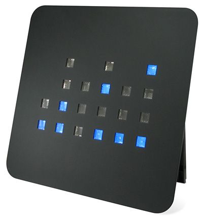
The black rectangle, in the diagram above, shows which leds you need to look at – the rest are not used in this project. You read the clock starting from the top and read horizontal row of four LEDs as a binary number. Each LED that is on represents a one and each LED that is off represents a zero. You then use the conversion table to translate it into decimal until you become so good at it that you won’t need the table!
Hardware
This project uses the same hardware as the led matrix project using a 16F88 PIC microcontoller and an LED matrix. Its worth taking a look there as the same hardware description applies on how to multiplex the display.
I’ll just say here that instead of using 64 output pins only 10 are needed to drive the display.
For more detail: Making a binary clock using a PIC16F88
- Can I use a PIC microcontroller for the binary clock?
Yes, the project uses a PIC16F88 microcontroller to drive the LED matrix. - How many LEDs are needed per decimal digit?
Four LEDs are used per decimal digit to represent numbers 0 to 9 in binary. - How many time digits are displayed?
Six decimal digits are displayed: hours (2 digits), minutes (2 digits) and seconds (2 digits). - Do I need 64 output pins to drive an 8x8 LED matrix?
No, multiplexing with the PIC16F88 reduces the requirement to about 10 output pins. - Can I use a 5x7 LED matrix instead?
Yes, you can use a 5x7 matrix by using the rightmost 4 columns and 6 rows for this project. - How is the time read from the LED matrix?
Read each horizontal row of four LEDs from top to bottom as a binary number, then convert to decimal using a binary-decimal table. - How are hours digits limited for a 24-hour clock?
For a 24-hour clock the most significant hours digit needs only 1 or 2 LEDs depending on the allowable range (0-2). - Is the same hardware used as other LED matrix PIC projects?
Yes, the hardware matches the LED matrix project that explains multiplexing using the PIC16F88.