Summary of 100KHz Square Wave generator using PIC16C84
This article describes a PIC16C84 assembly program (flashfast) that generates a ~100 kHz square wave by toggling PORTA.0 with 5 µs delays, intended as a simple oscilloscope test signal. It includes source, hex, and schematic, plus hardware notes for reset, PWRT, and an LED with a 220 Ω resistor on RA0.
Parts used in the PIC16C84 100kHz Square Wave Generator:
- PIC16C84 microcontroller
- 4 MHz crystal or oscillator (XT mode)
- 4.7 kΩ resistor (reset pull-up to Vcc)
- 220 Ω resistor (series with LED)
- LED
- Power supply (Vcc) and ground connections
- Optional programmer to load flashfast.hex
Following on from the LED flasher circuit, we can reduce the delay in the loop to 10uS (10 microseconds) and produce a 100Khz square wave.
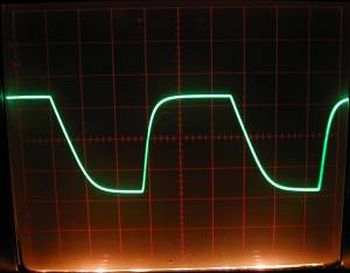
Given a 4 Mhz PIC 16C84, the program below will generate a 100Khz square wave on PORTA bit 0 (i.e. pin 17). This little program is useful for testing oscilloscopes (though it is not very accurate).
This program is available as:
- flashfast.asm assembly source
- flashfast.hex object file
- flash.jpg schematic
; Mark Crosbie  9/12/98
; Scope test program. Generate a 100Khz square wave.
;
;  The Program simply sets up Bit 0 of Port "A" to Output and then
;  loops, setting the value alternatively low and high
;
;  Hardware Notes:
;   Reset is tied through a 4.7K Resistor to Vcc and PWRT is Enabled
;   A 220 Ohm Resistor and LED is attached to PORTA.0 and Vcc
;
;	device	pic16c84

	include "p16c84.h"
   __CONFIG _CP_OFF & _WDT_OFF & _XT_OSC & _PWRTE_ON

;  Mainline of FlashFast

  org 0

  clrf   PORTA                  ;  Clear all the Bits in Port "a"
  clrf   STATUS
  bsf    STATUS, RP0            ;  Goto Bank 1 to set Port Direction
  bcf    TRISA, 0               ;  Set RA0 to Output
  bcf    STATUS, RP0            ;  Go back to Bank 0

Loop
  movlw 1                       ;  Turn on the LED on Port A
  movwf PORTA                   ;

  movlw 5
  call mdelay			; 5 uS delay

  movlw 0                       ;  Turn off the LED on Port A
  movwf PORTA                   ;

  movlw 5
  call mdelay			; 5uS delay

  goto Loop

; counter variables
For more detail: 100KHz Square Wave generator using PIC16C84
- What does this program generate?
It generates an approximately 100 kHz square wave on PORTA bit 0 by toggling the pin with 5 microsecond delays. - What PIC device is used?
The program is written for the PIC16C84. - What clock frequency is required to get 100 kHz?
The example uses a 4 MHz PIC clock to produce the approximate 100 kHz square wave. - How is RA0 configured in the code?
RA0 is set as an output by clearing TRISA bit 0 in Bank 1. - How are the high and low periods achieved?
The code writes 1 and 0 to PORTA with calls to a 5 microsecond delay routine between toggles to form the square wave. - What hardware is suggested for the LED connection?
An LED is connected to PORTA.0 with a 220 ohm series resistor to Vcc. - Are any configuration bits mentioned?
Yes; configuration disables code protection and watchdog timer, selects XT oscillator, and enables power-up timer (CP_OFF & WDT_OFF & XT_OSC & PWRTE_ON). - What files are provided with the program?
The assembly source flashfast.asm, the object file flashfast.hex, and a schematic flash.jpg are provided.