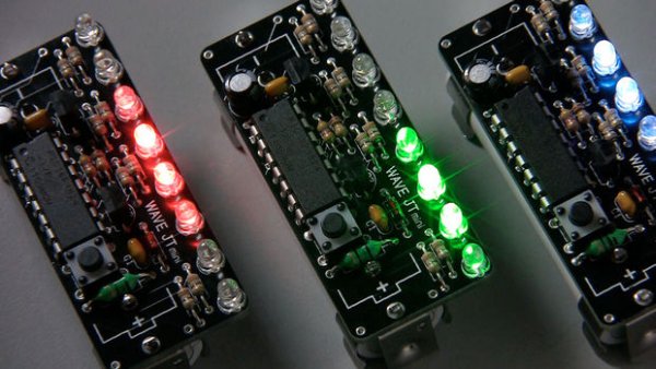
Summary of Wave JT – Larson Scanner with Joule Thief
Wave JT is a single-AA-battery powered LED chaser using a Joule Thief boost to run a PIC microcontroller. It drives eight LEDs with independent 8-bit (256-step) brightness using 31.25 kHz PWM, supports many animation patterns, speed control via multi-tap button, startup quick-select, and battery-aware regulation down to about 0.6–0.8 V. The microcontroller latches power, monitors supply via ADC, and modulates the booster to save energy.
Parts used in the Wave JT:
- AA battery (1.5V) or compatible 1.5V cell (NiMH/NiCd)
- Inductor (single-coil for Joule Thief)
- Two transistors (for Joule Thief)
- R1 resistor (bias resistor for Q2)
- Additional resistors (as required in circuit)
- Schottky diode D1
- Zener diode D2 (5.1V clamp)
- Capacitor C2 (output smoothing/rectifier capacitor)
- Microcontroller (PIC)
- Eight LEDs
- Button switch SW1
- Miscellaneous wiring, PCB or protoboard and connectors
I love LED chasers. A bunch of LEDs neatly turning on and off on a precise timing – lights running one way, then the other way… It’s relaxing, soothing, and hypnotic.
There are so many LED chaser/scanner/sequencer circuits out there, some are made with discreet transistors, some based on logic ICs, and more and more others are using microcontrollers.
There is one thing in common with all of the LED chaser circuits you find on the net – none of them can operate with just one alkaline battery!
Most of us know that LEDs need at least 2.2V or so to light. Blue and white LEDs require even higher, typically 3.2V. So obviously you can’t use just one AA battery to operate an LED chaser. But we all know that there is Joule Thief that boosts voltage high enough to light any LEDs. Why not use that to operate an LED chaser?
Missing Link
Joule Thief is a nickname for this simple voltage boost circuit, predominantly used to light LEDs with one battery cell. However Joule Thief can be used to power more than just LEDs. I decided to power a microcontroller circuit with Joule Thief. (Although I ended up still lighting LEDs.)
 Step 1: Features
Wave JT is not only powered by a single AA battery, but it’s feature rich. Here are the highlights of the Wave JT.
- Compact & streamlined design.
- Uses only one AA battery (or any 1.5V battery you can hook up to).
- Works well with rechargeables (NiMH or NiCd) too.
- Eight LEDs, each with its own 256 level brightness control.
- Energy efficient – works even with a run-down battery, down to 0.6V (0.8V to startup).
- Versatile PIC microcontroller based LED chaser/scanner/sequencer.
- Many light animation patterns to choose from.
- Speed control via multiple taps of a button (double/triple taps to speed up/down).
- Start up “Quick-select” mode to choose from top 8 of over 16 pat
Step 2: Technical Overview
Brief Background on Joule Thief
“Joule Thief” circuit is an inductor based voltage booster circuit to light LEDs with low supply voltage. The original circuit was published in 1999 and has been quite popular. You can see the principle of the circuit here: http://en.wikipedia.org/wiki/Joule_thief
My version is a variation that uses single coil inductor, to make the inductor easily obtainable. I designed the circuit using readily available parts only, to make it an ideal DIY project.
Why Joule Thief?
There are many options to create 5V from low voltage. First of all, there are many ICs made specifically for this purpose. Those ICs are usually simple to use, and very energy efficient. However they are not cheap – typically a few Dollars a piece.
Compare that with a Joule Thief – two transistors, two resistors, a capacitor and an inductor together is still cheaper than just the IC. Plus you know how the circuit works, instead of just taking a black box someone created. I think this is an important point for Makers.
As it turned out, a simple Joule Thief circuit that I used here is more than adequate for supplying power for microcontroller project. The fact that microcontroller can actively regulate the Joule Thief’s output voltage (more on this later) to improve overall efficiency makes this simple arrangement attractive.
Some Thoughts on Efficiency
I see a lot of discussion made about conversion efficiency of voltage converter circuit (Joule Thief included). No matter how efficient we make the converter, there will be some energy loss. So why use a voltage booster when you can simply use more batteries?
While a simple Joule Thief circuit like the one used with Wave JT does not have very high efficiency in converting voltage, it does allow us to use one battery instead of two or three. The net result is that there will be less batteries consumed because only one battery is used at a time (instead of two or three).
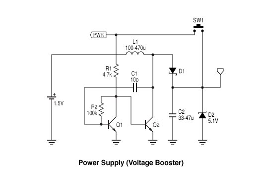
Step 3: Circuit
The power supply (voltage booster) part of schematic shows somewhat typical Joule Thief circuit, plus a few extra parts.
D1 (Schottky diode) and C2 form a rectifier to create DC voltage out of the Joule Thief. Zener diode D2 is added to “clamp” or limit the voltage at 5.1V to prevent damaging the microcontroller (maximum voltage this chip can withstand is 6V). Without the Zener diode there, the output voltage from the boost circuit can go over 6V when no LEDs are lit.
When the battery is first connected, the voltage charges the capacitor C2, then nothing happens until SW1 is closed. Once the SW1 is closed, current goes through R1 to turn on Q2, and the Joule Thief circuit starts working. In a fraction of a second, the voltage at C2 reaches high enough for the microcontroller to start up. Once the microcontroller starts running, it puts PWR signal high, so that the Joule Thief will keep running even after SW1 is open. (Power-on latch)
Note that after initial power up, microcontroller watches its own supply voltage via A/D converter and adjusts it slightly below the zener voltage, so to not waste precious power from the battery. “PWR” connection to the microprocessor does this by turning on/off bias current to Q2.
This “PWR” pin has two purpose; one is to control the booster circuit, the other is to read the status of the button switch. (this arrangement saves a precious microcontroller pin.)
 The button switch SW1 is more than a power switch, it provides pattern change, animation speed change (double tap to increase the speed, triple tap to decrease the speed). Microcontroller reads the button state by periodically turning the “PWR” pin into an input pin. This happens roughly every 8 milliseconds (125 times/second). The reading of the button takes about 2 microseconds each. The booster circuit turns off during this 2 microseconds, but it won’t be felt because capacitor C2 supplies the power during that period.
PWM LED Brightness Control
Each of eight LEDs can have its own brightness level. Brightness is specified (in firmware) in 8 bit number 0 – 255. Timer interrupt routine reads the brightness levels and turn on/off each LED accordingly, in sync with the hardware PWM signal. (PWM frequency is 31.25kHz. Interrupt occurs every 32 microseconds with firmware version 1.0)
Brightness change is very smooth – using the same PWM technique as my Aurora projects. Unlike other PWM implementations, the curve of brightness change is not linear, but exponent (anti-logarithmic). This is important because our eye’s response to brightness change is more or less logarithmic, therefore LEDs need to change brightness in the opposite fashion.
With Wave JT, the hardware PWM output is used as a precision clock to drive the LED bus (common line that connects to all LEDs) and “COLx” pins select which pulse to turn on the LED that’s connected to.
(Please see my Aurora 9×18 instructable for deeper explanation if you are interested.)
For more detail: Wave JT – Larson Scanner with Joule Thief
- Can Wave JT run from a single AA battery?
Yes. Wave JT is designed to run from one AA battery (or similar 1.5V cell) using a Joule Thief voltage booster. - What allows the microcontroller to run from the boosted voltage safely?
A 5.1V Zener diode (D2) clamps the boosted voltage to protect the microcontroller from exceeding its maximum voltage. - How many LEDs and brightness levels does Wave JT support?
Wave JT drives eight LEDs, each with 256 level (8-bit) brightness control. - How does the button SW1 function besides powering the device?
SW1 also provides pattern change and animation speed control via multiple taps; the microcontroller reads the button by briefly sampling the PWR pin. - How is PWM implemented for LED brightness?
Hardware PWM at 31.25 kHz is used; an interrupt every 32 microseconds updates LED states and brightness uses an exponential curve for perceptual smoothness. - Does the Joule Thief remain on after the button is released?
Yes. After startup the microcontroller sets PWR high to latch the booster on, so the system stays powered even when SW1 is opened. - How does Wave JT conserve battery power?
The microcontroller monitors supply via its ADC and adjusts the booster bias to regulate voltage below the zener, reducing wasted energy; it also works down to low voltages. - Can Wave JT start with a nearly drained battery?
Yes. It can operate down to about 0.6V, with startup typically around 0.8V.