Summary of Advanced Techniques for Fault Detection, Indication, and Protection in Induction Motors
Summary: This project uses a microcontroller-based protection system for a three-phase induction motor to detect and respond to overvoltage, undervoltage, overcurrent, undercurrent, and temperature imbalances. Instrument transformers, current and voltage sensors, an LM35 temperature sensor, relays, LEDs, and an LCD display provide monitoring, indication, and automatic motor shutdown until normal conditions return, protecting motor windings and improving reliability and lifespan.
Parts used in the Project:
- Microcontroller (central control unit)
- Potential transformer (instrument transformer for voltage)
- Current transformer (instrument transformer for current)
- Voltage sensors
- Current sensors
- LM35 temperature sensor
- Relays (for disconnecting motor)
- LED indicators
- LCD display
- Three-phase induction motor (protected device)
1. INTRODUCTION
The impact of microcontroller usage on our daily lives is remarkable. This versatile device is now prevalent in various control applications, utilizing a microprocessor as its central processing unit (CPU) while integrating features such as memory, timing references, and I/O peripherals on the same chip. In our project, the microcontroller plays a crucial role in controlling a three-phase induction motor.
Three-phase induction motors are extensively employed in industries as industrial drives due to their ruggedness, cost-effectiveness, reliability, and efficiency in transforming electrical power into mechanical power. Consequently, it is imperative to protect induction motors from potential faults that may arise during operation. Detecting and addressing faults promptly is essential, as undetected issues can lead to motor failure, a significant concern in industries and other settings where induction motors are widely utilized. Motor failure can result in production shutdowns and the loss of processing time.
Motor faults can stem from both electrical and mechanical issues. Mechanical faults, induced by overload or load changes, may cause bearing faults or rotor bar breakage in the induction motor. On the other hand, electrical faults are associated with power supply irregularities, such as overvoltage, undervoltage, overcurrent, undercurrent, temperature imbalances, single phasing, phase reversal, and overheating. In our project, we focus on specific faults like overvoltage, undervoltage, overcurrent, and undercurrent, as well as temperature imbalances.
To address these faults, our circuit is designed to detect and indicate them through displays and LEDs. Additionally, the circuit ensures the protection of the induction motor by cutting off power to the motor and switching it off when a fault is detected. The motor remains switched off until normal conditions are restored. We have implemented automatic control of the motor, allowing it to switch back on automatically once normal conditions resume [9].
2. REQUIREMENT AND IMPORTANT OF PROTECTION
Faults in induction motors arise from variations in parameters such as voltage, current, frequency, temperature, etc. It is crucial to safeguard the induction motor (IM) from these faults when it is in operation. When faults occur in the winding of the induction motor during its operation, the motor’s winding heats up, leading to potential failures or insulation breakdown and subsequently reducing the motor’s lifespan. Since a three-phase induction motor is directly connected to the power supply, any fluctuations in voltage and current due to faults can adversely impact the motor’s performance and may even result in the burning out of the winding.
Temperature variations also contribute to these issues, highlighting the importance of detecting and indicating faults in the induction motor. [1]
3. BLOCK DIAGRAM
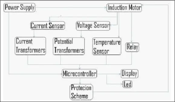
The presented block diagram above illustrates a straightforward representation of our project. At the core of this diagram is the microcontroller, which serves as the central control unit for the entire circuit and also manages the operation of the induction motor. Instrument transformers, specifically the potential transformer and current transformer, are linked to voltage and current sensors responsible for monitoring the voltage and current across the three phases. These transformers play a vital role in detecting variations in voltage and current. Subsequently, they provide feedback to the microcontroller, which, in turn, relays this information to the display for visual indication of voltage and current levels. Additionally, a temperature sensor is incorporated to monitor the temperature of both the winding and the induction motor.
In our project, the implementation of relays serves as a protective measure against faults arising from fluctuations in the parameters of the induction motor, including voltage, current, and temperature. Should any faults occur, the microcontroller receives feedback and activates the relays, leading to the circuit’s trip and the subsequent shutdown of the induction motor until normal operating conditions are restored.
4. OVER/UNDER VOLTAGE PROTECTION
Our voltage protection system for a three-phase induction motor serves to safeguard the motor from both overvoltage and undervoltage conditions, which refer to voltage levels exceeding or falling below the motor’s rated voltage. In our project, the initial step involves monitoring the voltage of the three-phase supply, and the circuit is designed to display key motor parameters. If the circuit detects deviations in voltage and current beyond predefined limits, it activates a mechanism to switch off the motor until normal conditions are restored. Voltage detection is achieved through instrument transformers, with the results indicated through LEDs and an LCD display. Furthermore, our paper or project employs relays to provide protection against these faults [4][5].
5. OVER/UNDER CURRENT PROTECTION
Our current protection system for the three-phase induction motor safeguards against both overcurrent and undercurrent. The overcurrent protection ensures that the motor is shielded from currents exceeding or falling below the rated current of the induction motor. In our undertaking, we initially monitor the current of the three-phase supply, and the circuit also provides indications for motor parameters. If the circuit identifies deviations in voltage and current beyond their set limits, it initiates the shutdown of the motor until normal conditions are restored. The current is detected using an instrument transformer, and the results are conveyed through LEDs and an LCD display. Our project employs relays to protect the motor from these faults as detailed in our paper [4][5].
6. TEMPERATURE IMBALANCE PROTECTION
Motor temperature imbalance protection aims to shield the motor from temperature fluctuations in both its winding and overall structure. Overheating issues arise from temperature imbalances, often triggered by motor overloading. When the motor is overloaded, it may struggle to initiate proper startup procedures, leading to motor failure caused by faults in the motor windings. To monitor temperature, an LM35 sensor is employed in our system. This sensor detects the motor’s heat and conveys this information through an LCD display. If the temperature surpasses a predetermined threshold, the LM35 sensor signals the microcontroller. The microcontroller, in turn, provides feedback to the protection system implemented in our project, prompting it to deactivate the motor until normal operating conditions are restored.
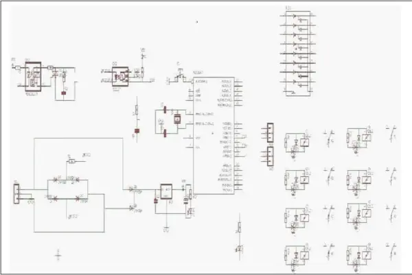
7. SCHEMATIC CIRCUIT IN EAGLE
8. CONCLUSION
In this paper and project, we address various faults, including overvoltage, undervoltage, overcurrent, undercurrent, and temperature imbalances, with the aim of ensuring the smooth and safe operation of the motor. This approach enhances the efficiency and extends the lifetime of the motor. Typically, these faults arise when the supply system exceeds its specified rating. In the case of a three-phase induction motor operating at its rated value, these faults do not occur.
- What faults does the project detect?
The project detects overvoltage, undervoltage, overcurrent, undercurrent, and temperature imbalances. - How are voltage and current monitored?
Voltage and current are monitored using potential and current transformers connected to voltage and current sensors. - How is temperature monitored?
Temperature is monitored using an LM35 temperature sensor that reports winding and motor temperature to the microcontroller. - What happens when a fault is detected?
The microcontroller activates relays to trip the circuit and switch off the motor until normal conditions are restored. - How are motor parameters indicated to users?
Motor parameters and fault indications are shown on an LCD display and via LED indicators. - Does the system restart the motor automatically after a fault?
The project implements automatic control allowing the motor to switch back on automatically once normal conditions resume. - Why is protection necessary for induction motors?
Protection is necessary because faults can overheat windings, cause insulation breakdown, reduce motor life, and lead to production shutdowns. - What role do relays play in the protection system?
Relays disconnect power to the motor when faults are detected, providing protective shutdown until conditions normalize.