Summary of Whistle Controlled Light Switch
Summary (under 100 words) A whistle-controlled light switch uses a microphone, amplifier with DC offset and low-pass filter, ADC on a PIC32, FFT-based peak-frequency whistle detection, and a Finite State Machine that recognizes 3-step monotonically increasing/decreasing whistle melodies to command a continuous-rotation servo that physically toggles a standard US wall switch. Sampling is 8 kHz with 256-sample FFT buffers; hardware amplification and filtering prevent aliasing and reduce software load. The system was calibrated for torque, PWM control, and debounce against false positives; mount printed in 3D and mechanical linkages were iterated for reliable switching.
Parts used in the Whistle Controlled Light Switch:
- Hosiden electret condenser microphone
- Non-inverting amplifier circuit (op-amp, resistors including 2 MΩ and 5 kΩ, coupling capacitor)
- DC offset supply (1.65V reference)
- Low-pass filter (cut-off ~3500 Hz)
- PIC32 microcontroller (with ADC and DSP/FFT library)
- Timer 2 for ISR
- 256-sample ring buffer (software component)
- FeeTech FS5103R continuous rotation servo
- 6 V battery pack (servo power)
- 330 Ω series resistor (in servo power line)
- 4-arm servo horn and arm attachments (mechanical linkage)
- 3D-printed mount (modified CAD design)
- TFT display (used for FFT output testing)
Introduction
For our final project, we built a whistle controlled light switch. We were motivated by the daily struggle of getting out of bed to turn on/off the light. You can attach our final product on any light switch that can be commonly found in U.S. households. Once a correct sequence of whistle frequencies is detected, light switch will be mechanically toggled. You can turn on the light with a monotonically increasing whistle melody, and turn off with a monotonically decreasing.
Overview
Rationale and Sources for Project Idea
The idea of the project is to remotely control a wall light switch. Reflecting the rise of home automation these days, there already exists a remotely controllable light bulbs like Philips Hue which can be controlled through smart devices like an iPhone or Amazon Echo. However, these new home automation devices have to be installed separately and there is no appropriate solution for making an already installed wall light switch, which is common in many households, remotely controllable. Thus, we propose a device which can be mounted next to a wall light switch to turn the light on and off via whistle commands.
Background Math
The approach we took for the whistle recognition is a simple detection of a peak frequency. We differentiate a whistle from voice by looking at the ratio between frequencies with two highest magnitudes. A ratio above certain threshold is considered as a single detection. Then, the system uses a final state machine (FSM) to detect monotonically increasing/decreasing whistle melody, which consists of 3 consecutive detections.
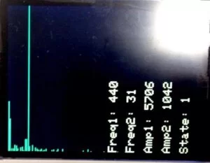
In order to detect features from a sound wave, we first need to convert the time-domain signal to the frequency-domain data. A French scientist and mathematician Jean Baptiste Fourier proved that any periodic waveform can be expressed as the sum of an infinite set of sinusoids. Thus, expressing the sound signal as a linear combination of sinusoids of different frequencies makes it easier for us to detect a feature in the signal. In order to do this, we need to compute Discrete Fourier Transform (DFT) of the input signal. We use a fast Fourier transform (FFT) algorithm that reduces the complexity of computing the DFT from O(n2) to O(n log(n)). For software implementation, we use the existing DSP Library for PIC32. We tested the output of the FFT algorithm, using the TFT screen. In the Figure 2-1 below, we can see that 440 Hz frequency is detected with the highest magnitude when we generated a 440Hz tone using online tone generator.
We found out that a typical whistle frequency band ranges from approximately 500 Hz to 5000 Hz. In order to get a better granualarity of data, we set the maximum frequency that should be detectable by the light switch to be 4000 Hz. By the Nyquist-Shannon sampling theorem, the sampling rate must be at least twice the highest analog frequency component. Thus, the sampling frequency has to be 8000Hz. In other words, we have set-up our software such that we take in the ADC reading every 1/8000 = 125 ms (one sample per 125 ms).
Given that we want our sampling frequency to be 8000 Hz and our system clock frequency is 40 MHz, we set up the software such an ISR to read in the ADC value is triggered once every 5000 system clock ticks. We used a buffer size of 256 as an input to one FFT calculation. Then, we fold the symmetric output result into one-sided frequency spectrum. Therefore, we had 128 frequency buckets for the range from 0 to 4000 Hz. This means that the granualarity of our data is limited by about 31.25 Hz per frequency bucket.
In order to successfully flip a toggle light switch upon detection of the whistle signal, we needed to ensure that our motor would be able to provide enough torque. By using a weight of predetermined mass attached to a light switch, we were able to determine the amount of force necessary to flip the light switch. Through experimentation, we found that an object of mass 107.5 g was enough to pull down a light switch. This gives us 0.1075 kgf as the amount of force needed to flick a light switch on or off.
We chose the FeeTech FS5103R Continuous Rotation Servo for our motor due to its ease of use and our familiarity with the product. Its stall torque at 6 V is about 3.2 kgf-cm. Given this maximum stall torque, we can calculate the maximum distance the rotation axis of the motor can be from the light switch to provide enough force to flip it, as shown in Figure 2-2.
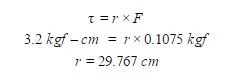
The results of the equations above tell us that the furthest our servo can be from the light switch while still being able to flip it is a bit less than 30 cm. This is more than enough torque and gives us more than enough room for error for our application. With this, we were able to verify, at least theoretically, that our servo should have no problem turning the light switch on and off.
Logical Structure
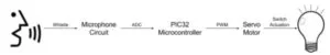
The logical structure of our project is shown in Figure 2-3 above. First the whistle is picked up by the microphone and makes its way through the circuit where it is amplified and filtered. Then the analog input is converted to digital using the on-board ADC on the PIC32. Once some computation is done in processing the signal, a PWM is output to the servo motor, which controls physically actuating the switch to turn the light on and off.
Hardware/Software Tradeoffs
For our design, we had a choice of implementing the amplifier and low-pass filter on either hardware or software. The software implementation would be very straight forward: multiplying the value by a constant for amplification and filtering the frequencies by setting some threshold values for low-pass. However, we chose to go with hardware implementation for both. First, implementing the amplifier on the hardware takes strain away from software computation. An ISR to read the ADC value happens 8000 times per second. Implementing amplification on software requires multiplication everytime the ISR is called. A multiplication might seem trivial, but any burden on software computation can cause a timing issue on other major implementations. Next, implementing the low-pass filter on hardware prevents aliasing. Since the ADC readings are the direct input to the FFT algorithm, limiting the input signal from 0 to 4000 Hz becomes crucial for our implementation. Filtering frequencies on time-domain signals on software is actually a tricky problem.
Standards
Our project follows the IEEE Code of Ethics, which highlights the importance of the highest ethical and professional conduct.
Related Copyrights and Existing Patents
There exists a patent Apparatus and Method for Control Using a Humming Frequency (20110051557) regarding the use of human whistle or humming frequency as a method for control.
Design
Hardware Design
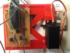
Our hardware design consists mainly of a microphone to detect the voice commands, a servo motor to toggle the light switch, and the mount to hold everything next to a wall light switch.
Microphone Circuit
We begin with a basic microphone circuit. We used a Hosiden’s electret condenser microphone.
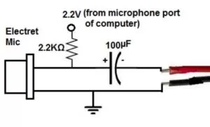
In the Figure 3-1, the microphone is powered with 2.2V. The capacitor is connected in series to the output of the microphone in order to remove the DC offset created by the DC voltage used to power the microphone. In that way, we only see the AC signal on the output.
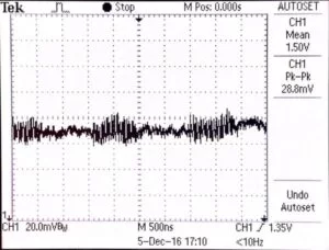
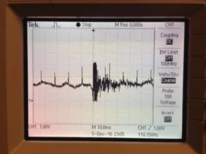
Once all these connections were made, we tested the microphone. The micrphone functioned correctly, but we realized that the amplitude of the AC signal is way too small to detect. In Figure 3-2, we can see that the signal oscillates only within 20mV with an “Ah” sound. Thus, we decided to amplify the output signal using a non-inverting amplifier so that the resulting signal will be appropriate for the ADC input for the PIC32.
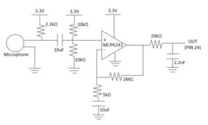
In Figure 3-3, we add a non-inverting amplifier to the output of basic microphone circuit. As mentioned before, in order for the final output of the microphone circuit to be an appropriate input of PIC32’s ADC, we need to make the values to range from 0 to 3.3V (0-1023). First, we add 1.65V DC offset to the output of the microphone circuit to so that the signal floats at the median value. Then, we use a non-inverting amplifier with a gain of 401 to amplify the AC signal. The value of gain can be adjusted using the proportion between the two resistor values in the feedback loop. Here, the gain equals 1 + (2MOhm/5kOhm) = 401. By adding a capacitor in series of the 5kOhm resistor, we can amplify just the AC part of the signal. This is necessary because we will saturate the circuit if we amplify the DC part of the signal as well. (1.65V * 401 = 661.65V is way too big.) Lastly, we apply low pass filter with the cut-off frequency of about 3500Hz to the output in order to prevent aliasing. As mentioned before, the final output signal will be connected to the pin 24 of the PIC32 as an ADC input.
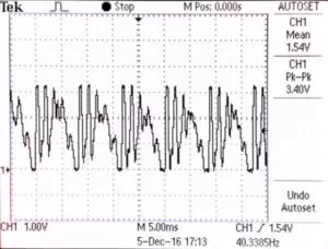
Once we finished the circuit in Figure 3-3, we could see that an “Ah” sound generates a signal with a DC offset of about 1.54V and peak-to-peak amplitude of about 3.4V.
Servo Motor
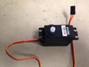
The FeeTech FS5103R Continuous Rotation Servo, shown in Figure 3-5, interfaces with any hardware via 3 analog wires. The brown wire is ground and is expected to be the shared ground between the power source and the control source. The red wire is power. The operating voltages for this servo range between 4.8 V and 6 V, though 5 V is recommended. For this project, we used a 6 V battery pack in order to draw maximum torque from the servo. Finally, the orange wire is the control. In order to control the FeeTech servo, a 50 Hz PWM signal must be used with a duty cycle ranging from 5% to 10%. In other words, for a PWM signal with a period of 20 ms, a 1 ms pulse produces full speed backwards, a 1.5 ms pulse is used for a full stop, and a 2 ms pulse produces full speed forwards, where “forwards” refers to counterclockwise facing the horn of the servo. In order to be safe, we included a 330 Ω resistor in series with the power supply, as shown in Figure A-1 below in the appendix.
Another reason we chose this continuous rotation servo is that it can turn in both directions with only a slight change in the PWM output. This allowed us to implement our project without the need to build an H-bridge circuit, which is typically used to provide negative voltages to motors to spin them backwards. Since the PWM signal can be completely controlled in software without any additional hardware components, interfacing with the servo was quite simple and problem-free. However, one particular issue we ran into was in failing to realize that ground of the PIC32 and the ground of the power supply must be shared such that all voltages are in reference to each other. Without this detail, the servo will not run.
Much of the time spent working on motor design was not with the electrical characteristics of the motor but rather its mechanical characteristics. Part of the design problem was in deciding a configuration in 3D space for our motor that would be able to reliably flip the switch on and off. The configuration in our final design consisted of using the 4-arm horn and bolting 2 support attachments to 2 of the arms and attaching a third link to both support attachments. This configuration is shown in Figure 3-6. As the motor rotated clockwise, the upper arm would push the switch down and as the motor rotated counterclockwise, the lower arm would push the switch up. Some failed configurations that were attempted before arriving at the final design are discussed below.

Mount
The mount for the motor was modified from an existing publicly licensed project we found. This project also attempted to control a light switch through the use of a servo and a microcontroller. Unfortunately, since the creator had used the SG90 Micro Servo, which is about a quarter of the size of the servo we used, we had to modify the mount design in order to fit our servo’s dimensions. Specifically, we had to modify the spacing between the servo supports as well as the height and the number of holes. The SG90 Micro Servo has only one screw hole on each side of the servo, whereas our FeeTech servo has two screw holes on each side. We also enlarged the circuit space on the mount itself, in order to allow for our larger hardware. The project link is given in the references below.
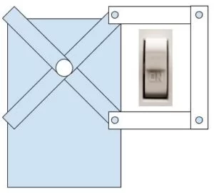
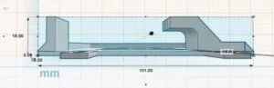
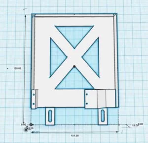
The mount was modified using the online cloud-based CAD software called TinkerCAD, also linked below. Our final mount design is shown in Figures 3-8 to 3-11. The large ovular holes in the front are where the screws in the light switch housing would go, to keep the device in place and attached securely to the light switch. The distance between the holes was measured to be exactly the standard distance between screw holes on light switch housings. The servo would sit facing down on top of the supports and screwed into the holes in the supports. The distance between the supports was designed such that the axis of rotation would sit midway between the light switch housing holes, such that the rotation axis would be centered to the light switch itself.
Once we finished the CAD model of the mount, we had it 3D printed and made some minor adjustments to the finished model in preparation for our demonstration.


Software Design
Timer 2 Interrupt Service Routine (ISR)
We configured timer 2 to generate a periodic interrupt every 5000 system clock ticks. Inside the ISR, we grab the Analog to Digital Converter value of the sound signal sampled through the microphone. This sample value is then appended to a ring buffer such that a new value will overwrite the oldest value in the buffer. With the size of 256, the buffer can hold up to 32 ms of sound signal
FFT Protothread
Most of the work is done in the FFT Protothread including FFT calculation and the whistle recognition algorithm. The computeFFT() function works by reordering the collected sound signal samples in chronological order from lowest index to highest index. This reordered buffer is then passed as an argument to PIC32’s DSP library function for computing FFT. Given the conjugate complex symmetry of the transformed output, we computed the single sided FFT by only considering one side of the symmetry.
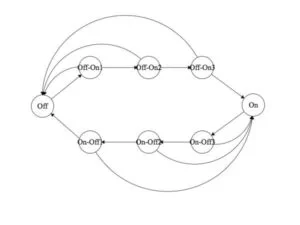
We used a finite state machine to implement the whistle recognition system. The idea is to look for a “sharp peak” in the frequency domain. A sharp peak refers to the frequency with the highest amplitude greater than the second highest amplitude by a scaling coefficient. As human’s whistle generates a relatively clean sine wave, we used the idea that there will be one dominant frequency distinguished by a much higher amplitude. To compute the ratio of the highest to second highest amplitudes, we iterated over the array containing the single sided FFT and looked for the top two frequencies with the highest amplitudes. In order to take the signal noise into an account, when looking for the second highest peak, we disregarded frequencies that are within 32 Hz of the highest amplitude frequency.
Once the sharp peak is detected, the system changes its state to an intermediate state. There are a total of three intermediate states in between the ON and OFF states. These states ensure that the input signal’s sharp peak is monotonically increasing or decreasing by comparing the current and previous sharp peaks. At each intermediate state, the state machine either moves on to the next state if the peak frequency is monotonically increasing/decreasing and the amplitude of it is above a pre-set threshold (we found 1000 to be working the best) or revert back to ON/OFF state after a 2 second timeout. Finally, when the system fully recognizes a monotonically increasing/decreasing whistle signal, it sends PWM signal to the connected servo motor to rotate its gears to turn on/off the light switch.
In order to ensure that the state machine can correctly detect the monotonicity of a whistle up or whistle down sound, we scheduled the FFT Protothread to run every 128ms. A regular whistle up/down sound has an average rate of change of 50 Hz/200 ms. Since the frequency bins of the FFT array are 31.25 Hz apart, a 128ms gap between each FFT computation allows the system to detect at least one frequency bin change from the previous peak frequency.
Previous Design Attempts
Hardware: Motor Configurations
During our initial design consideration for the motor configuration, one of our more favored designs is shown in Figure 3-12 and Figure 3-13. This design shows the motor rotation axis on the same plane as the light switch and provides a more intuitive flipping on and off motion by providing forces ideally perpendicular to the counterforce in the switch. We decided ultimately against implementing this design because although it would be more effective in translating rotational torque to the force needed to flip the switch, it would be much more difficult to build mechanically. Additionally, we decided that we had more than enough torque to compensate for a slightly less effective design, if it meant that it was simpler.


Before arriving at the final design for our motor configuration, as shown in Figure 3-6, we experimented with many different failed configurations. Initially, we attempted to flip the light switches without the arm attachments and only using the 4-armed horn. However, we soon discovered that the horn was not long enough to reach the light switch given our mount dimensions. We add the 2 attachments as a means of lengthening our horn arms. Initially, we bolted the attachments parallel to the horn arms to simply lengthen them. However, upon testing we realized that the arms became too long to allow the full 90 degree rotation necessary to flip the switch. The next configuration was achieved by skewing these attachments so they were parallel to each other but not to the horn arms themselves. This gave enough room to rotate fully, while providing enough contact with the light switch. Although everything seemed like it would work, we discovered yet another bug in our design. Simply bolting the attachments to the arms once did not provide enough constraints to fix the arm angles. We found that as the servo rotated the arms, the attachments became loose and simply rotated about their bolts but did not flip the switch. The final edition to our design was the last vertical piece shown. This last piece was meant to fix the angles between the attachments and the horn arms such that the attachments could not skew away and the majority of the torque was transferred to flipping the switch. With experimentation and testing, we were able to verify that this final design was stable and consistent in its ability to flip the light switch on and off.
Software: Voice Recognition 1 – Voice MFCC
Initially, we attempted to implement a speech recognition system using the Mel-frequency cepstrum (MFCC), a representation of the short-term power spectrum of a sound that is widely used in speech recognition. The idea was to generate a template MFCC for the chosen speech commands (ex. “turn on,” “turn off”) and dynamically match the input speech signal against the template to determine whether there is a match. We used libmfcc, a C library for computing Mel Frequency Cepstral Coefficients given the FFT of the sound signal, to compute MFCC on the fly in PIC32 program. However, we ran into issues with the runtime complexity of computing MFCC dynamically. According to our measurements, it takes about 250ms for computing one MFC coefficient for an FFT buffer of size 128 and 700ms for computing two coefficients, resulting in an uncompromisable delay.
Software: Voice Recognition 2 – Sequence of Frequencies
After realizing the difficulties of implementing MFCC speech recognition on PIC32, we moved on to a much simpler version of speech recognition. Motivated by how much a smart phone is integrated in our daily lives, we thought that it would be practical to use a tone generator from a smart phone to generate a sequence of frequencies and remotely control the light switch. We used a finite state machine to recognize the sequence of two frequencies. Similar to the whistle recognition FSM, the system transitions to the next state after detecting a target frequency with an amplitude above the pre-set threshold. Once both of the frequencies are detected in sequence, the system sends PWM signal to the servo motor to turn the light switch on/off. This version had a high accuracy with a low possibility of false trigger.
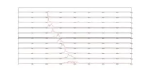
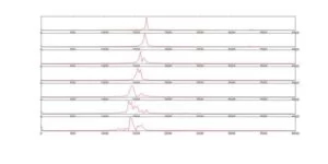
Software: Clap Recognition
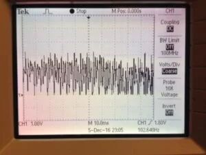
We tried implementing a light switch toggled by a clap. Since a clap sound does not have an interesting feature in the frequency domain. We looked for features directly in the time-domain. As in the Figures below, We saw that the duration for peak-to-peak sound lasts much shorter for a clap, compared to a short burst of voice. First, we tried to count the number of peak amplitudes in a time window. If the count goes over a threshold for one to five time windows, we considered it as a clap and triggered an action; else, we ignore the sound. However, this didn’t work well as we expected because the ADC readings are sampled and the values does not reach the peak-to-peak value as frequently as we hoped. Then, we tried to take an average power in the input sound and compare it against a threshold. This implementation worked well for a clap, but it was also often triggered by false positives. After some investigation, we realized that our ADC readings are limited because our amplifier circuit design was tuned for normal voice recognition, thus having too much amplification. Such amplification resulted into the clipping of the output voltage, so the signal above certain low threshold amplitude is all considered as a large sound. This made it harder to differentiate clap and voice, even though a clap usually generates a sound wave with much higher amplitude than even a short burst of voice.
Results
Accuracy
We used a buffer size of 256 as an input to one FFT calculation. In other words, everytime we take 256 samples, we run one FFT calculation. Since the output result is symmetric about 0 Hz frequency, we fold the result into one-sided frequency spectrum, giving us 128 frequency buckets on the frequency range from 0 to 4000 Hz. This means that the accuracy of our data is limited by about 31.25 Hz per frequency bucket.
As mentioned above as a limitation to clap recognition, the non-inverting amplifier amplifies the input signal by factor of 401. In addition, the range of input signal to our software system is limited by the ADC input (0-3.3V). Therefore, such large amplificaiton of the sound signal constrain the system’s ability to differentiate signals with high amplitudes, as the system will be saturated with a voltage higher than 3.3V and consider those values as the maximum (3.3V – 1023).
Motor Calibration
Interfacing with the FeeTech servo motor consisted not only of setting the correct PWM duty cycle but also in tuning the servo such that it behaved as expected. As mentioned above, the servo is expected to stop completely and not provide any torque to either direction if the PWM signal has a 1.5 ms pulse or a 7.5% duty cycle for a 50 Hz signal. Inside the servo there is a potentiometer that must be tuned such that this behavior is achieved. As we discovered during testing, tuning the servo is not only important to achieve expected behavior of the servo but it is also incredibly crucial to achieve expected behavior of the microphone circuit and our product as a whole. This is due to the fact that while the servo is turning, there is a tremendous amount of noise and jitter generated by the sound of gears turning. Since the servo was placed so close to the microphone itself, this effectively drowned out any other input we were possibly hoping to recognize. That being said, it was not an issue if the program expected the servo to be running, since we don’t care about microphone data during that time. However, if the program expects the servo to be still and begins collecting microphone inputs while the servo is untuned, the servo can unexpectedly jitter and generate noise that completely renders our input useless. Therefore, we found that it is crucial to re-calibrate the servo before every single use.
Speed of Execution
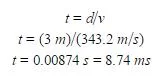
The speed of execution of our product is determined by a large variety of factors, ranging from the speed of sound in air to the delay due to FFT computation to the frequency at which we sample the input signal. For starters, the speed of sound in air is about 343.2 m/s. Given that we had been able to successfully test our system up to a range of about 3 meters, we can calculate the amount of delay between when we whistle to when the system detects it, as shown in Figure 4-1.
Our sampling frequency, mentioned above, is 8 kHz. That means that a new sample is taken once every 0.125 ms. In the worst case scenario, a given sample of speech will be delayed by 0.125 ms. Additionally, we are running our detection loop at a rate of once every 128 ms. This is where the bulk of our delay comes in. As explained above, we run our detection loop at this rate in order to disambiguate voice signals and whistle signals and to allow the whistler some leeway in the amount of time it takes to monotonically increase or decrease the pitch enough for our program to understand. Furthermore, our state machine has four states through which one must pass in order to flip the light switch on or off. In the worst case scenario this results in four times the delay of our detection loop for each state. Finally, at the state that outputs the PWM, we have found that outputting the proper PWM for about 200 ms was sufficient in turning the switch on or off. This manifested itself as a PT_YIELD_TIME_msec command, which adds a delay of about 200 ms to our whole process. In total, the delay in the worst case is given below in Figure 4-2.
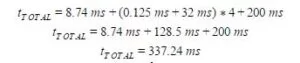
In other words, it takes a bit more than one-third of a second between a given whistle to the time when the light has been turned on or off. However, this is assuming that the whistle was recognized perfectly. If the system is improperly tuned, it is likely to take even longer, since our state machines are set up such that if the whistle is not monotonically increasing or decreasing, depending on the state, one must start back from the beginning again.
Conclusion
Expectations and Future Work
Although it was unfortunate that we were unable to accomplish pure voice recognition, it is doubtful that we ever would have been able to given our limited hardware and limited time constraints. We feel as if we had been too hopeful and naive to initially set voice recognition as our goal. That being said, the ability of our system to recognize whistles was for more reliable and accurate than we expected. Our results surpassed our expectations in both software and hardware, in terms of physically being able to flick the switch up and down. We attest that we were able to build a reliable and consistent whistle detection system that can also reliably and consistently turn a toggle light switch on and off.
Despite having met and exceeded our expectations, there are a few key points that we can carry with us the next time we endeavor on a similar project. First and foremost, it was imperative that we realize early on that speech/voice recognition was an ambitious goal. We had assumed that once we put all the components in place, everything would work. What we had failed to foresee is how computationally heavy MFCC calculations were and how limited our memory was on the PIC32 microcontroller. We also realized that there were a lot of aspects of speech/voice processing that we were unfamiliar with. We learned that it was not as simple of a task as we had hoped and would take that into consideration for the next time we attempt it.
In terms of future work to be done for our project, there are quite a few optimizations and enhancements we could make to our system. For one, as seen in the video, our system is great at minimizing false negatives; generally speaking we never had to whistle more than twice in order to have the system recognize the command. However, it is not so great at minimizing false positives. We found that normal conversation can potentially trip our system, given the innate tonal fluctuations in language and especially the common decreasing tonal inflections at the end of a sentence. In order to better protect against false positives, we could tune our system more precisely, taking into account more of the inherent differences between speech and whistles. Additionally, we could have modified our state machine to more strictly guard against clearly non-whistle signals by imposing a higher signal peak ratio threshold or a greater monotonically increasing or decreasing threshold. Given more time, we could have experimented more with the delay between each FFT computation loop and its effect on precision and accuracy.
Overall, we felt that as a group we were able to pull out a very well-behaved system from non-ideal circumstances. We felt that we learned a lot about speech processing and frequency computation, as well as signal processing in general. We were also able to gain some experience using CAD and designing mechanical components as well as electrical ones. We feel satisfied with our experience and agree that this project was ultimately successful.
Intellectual Property Considerations
We credit Professor Bruce Land for the implementation of configuring the internal Analog to Digital Converter of PIC32 and performing Pulse Width Modulation. We also referred to Northwestern’s Neuroscience and Robotics Lab’s code on executing Fast Fourier Transform in PIC32.
Ethical Considerations
We believe that in creating our system to be as reliable as possible we are abiding by the IEEE Code of Ethics in “making decisions consistent with the safety, health, and welfare of the public.” In terms of possible safety and health concerns, we foresee that constant flickering of lights can cause dizziness or confusion or even trigger an epileptic episode. In constantly attempting to tune our system to be more resilient to noise and false positives, we have done our best to ensure that our system behaves as expected and not randomly or unexpectedly. Additionally, with many of our failures and faults we have discussed in this report, we feel that we have been “honest and realistic in stating claims or estimates” about our system. We have not attempted to oversell our project nor have we taken any bribes to complete it. Additionally, we don’t believe that our product discriminates based on “race, religion, gender, disability, age, national origin, sexual orientation, gender identity, or gender expression.” In fact, the only people we foresee as having trouble using our system are those who cannot whistle, but I would hardly call not being able to whistle a disability. And even for possible patrons who cannot whistle, there are many ways to avoid having to whistle, such as using a tone generator on a mobile phone or computer to generate the frequencies needed to turn on and off the light switch. Albeit this method is quite counterproductive to our goal of remote control, we affirm that we have tried our best to extend the functionality of our product to all people. We believe that we have abided by all of the other statements in the IEEE Code of Ethics not explicitly mentioned here.
Legal Considerations
In terms of legal considerations, there are no standards that we must abide by except for ensuring that the input signal threshold not be above any harmful noise level standards. We have designed our system such that the noise level generated while interacting with our system should not be in violation of any noise regulations. We did use libraries that other people have written in our program as well as modified the CAD model that someone else had created to fit our project’s needs, but we have ensured that everything we have used from third parties is protected under public licensing, so as long as we do not attempt to pass these components on as of our own design, we are in the clear.
Source: Whistle Controlled Light Switch
- How does the system detect a whistle?
It computes an FFT of ADC samples and looks for a sharp peak where the highest amplitude exceeds the second highest by a threshold, then uses a finite state machine to verify monotonic pitch changes. - What sampling rate and FFT size are used?
Sampling rate is 8000 Hz and FFT buffer size is 256 samples, producing 128 one-sided frequency bins up to 4000 Hz. - Can the device flip a standard US wall light switch?
Yes; a continuous rotation servo with measured stall torque and mechanical linkage was used and experimentally verified to flip a switch using about 107.5 g force. - Why is hardware amplification and filtering used instead of software?
Hardware amplification reduces software load from repeated multiplications in the ISR and hardware low-pass filtering prevents aliasing before ADC sampling. - How does the servo get controlled?
The FeeTech FS5103R servo is driven by a 50 Hz PWM from the PIC32 where pulse widths from 1 ms to 2 ms control rotation direction and 1.5 ms stops it; a 6 V battery pack powers the servo. - How does the FSM determine an on versus off command?
The FSM requires three consecutive detections showing monotonically increasing peaks to turn on, or monotonically decreasing peaks to turn off, with amplitude thresholds and timeouts. - What causes false positives and how might they be reduced?
Conversation tonal fluctuations can trigger the system; the article suggests tuning the peak ratio and monotonicity thresholds or adjusting FFT timing to reduce false positives. - What is the system's worst-case delay from whistle to switch toggle?
Worst-case delay is a bit over one-third of a second, considering sampling, detection loop (128 ms per FFT), state transitions, and a ~200 ms PWM actuation time. - Why was MFCC-based speech recognition not used?
MFCC computation on the PIC32 was too slow and computationally expensive, causing unacceptable delays (hundreds of milliseconds per coefficient).