
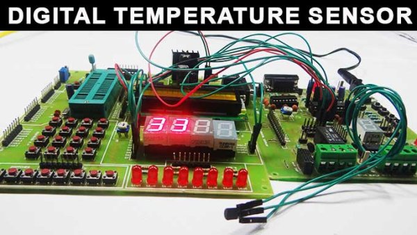
Summary of Digital Temperature Sensor Circuit
This article explains a digital temperature sensor using an ATmega8 microcontroller and an LM35 sensor. The LM35 analog output connects to the ATmega8 ADC (PC0), which performs 10-bit successive approximation conversions; results drive a common-cathode 7-segment display on Port B through current-limiting resistors. Vref and AVcc must be connected for ADC operation, and ADC registers configured to enable Port C ADC function. Multiple ADC channels (PC0–PC5) are available but only one channel converts at a time.
Parts used in the Digital Temperature Sensor:
- Resistors R1 to R7 (330 Ohms each)
- LM35 Temperature sensor
- ATmega8 Microcontroller
- 7 Segment Display (common cathode)
Temperature sensors are widely used in electronic equipments to display the temperature. You can see the digital clock displaying the room temperature value. It is due to the temperature sensor embedded in it. Generally, temperature value is analog. It is converted to digital value and then it is displayed. This article describes the same converting analog value to a digital value.
Digital Temperature Sensor Circuit Principle:
The main principle of this circuit is to display the digital temperature value. Here, ATmega8 microcontroller is used. The ATmega8 has inbuilt analog to digital converter with six multiplexed channels. This reduces interfacing of external analog to digital converter IC. The analog temperature value is directly applied to input ADC channels of microcontroller. Successive approximation method is used for Analog to digital conversion internally.
Digital Temperature Sensor Circuit Diagram:
Circuit Components:
- Resistors – R1 to R7 having the value of 330 Ohms each.
- LM35 Temperature sensor
- ATmega8 Microcontroller
- 7 Segment Display
Digital Temperature Sensor Circuit Design:
The digital temperature circuit consists of ATmega8 microcontroller, LM35 temperature sensor, 7 segment display. The temperature sensor Lm35 is connected to one of the ADC channels of microcontroller.
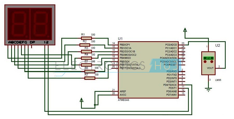
ATmega8 has six ADC channels at Port C. PC0-PC5 pins of Atmega8 act as ADC channels. This shows that one can interface six analog values. But only one conversion is done at a time depending on the priority of the input channels. The resolution of ADC is 10 bit. Remember that for conversion Vref and Avcc are externally connected as shown in circuit.
Generally, all the port pins of ATmega8 microcontroller act as normal input /output pins until their special functions are declared. ADC registers inside the controller have to be declared in order make Port C to act as ADC channel.
Lm35 temperature sensor has three terminals. Placing the flat surface towards you first pin is Vcc, Second pin is Output and the third pin is Ground. Output pin of temperature sensor is connected to the first ADC channel i.e. PC0 pin of microcontroller.
Seven segment display has eight pins and one common pin. Leaving Dp, connect all the seven pins to port B. Connect A to PB0, B to PB1,_____, G to PB6. Seven segment display used here is common cathode display. Current limiting resistors were used between controller and the display.
For more detail: Digital Temperature Sensor Circuit
- How is the analog temperature value converted to digital?
The ATmega8 internal ADC uses successive approximation to convert the LM35 analog output to a 10-bit digital value. - Which ADC channel is the LM35 connected to?
The LM35 output is connected to ADC channel PC0 of the ATmega8. - Do I need an external ADC IC for this project?
No, the ATmega8 has an inbuilt ADC with six multiplexed channels, so no external ADC IC is required. - What display is used to show temperature?
A common cathode 7-segment display connected to Port B is used to show the temperature. - How are the 7-segment pins connected to the microcontroller?
The seven segment pins (excluding the decimal point) are connected to PB0 through PB6; A to PB0, B to PB1, up to G to PB6, with current-limiting resistors. - What is the ADC resolution of the ATmega8?
The ATmega8 ADC resolution is 10 bit. - Are Vref and AVcc connections required?
Yes, Vref and AVcc must be externally connected for proper ADC conversion as shown in the circuit. - How many analog inputs does the ATmega8 provide?
The ATmega8 provides six ADC channels at Port C (PC0–PC5) for analog inputs.
