Summary of Microcontroller Implementation of a Small Robot Arm Controller
Summary: The project develops assembly-language control software and interface circuitry for a robot arm using an enhanced 8051 (80535) microcontroller and an EMAC I/O board. It includes safety features (motor current limit and motor disable), keypad/LCD user interface, D/A monitoring channels, PID control running at 200 Hz, power amplifier and motor/geartrain from Quanser, position feedback via potentiometer with antialiasing filter, and planned performance measurements versus MATLAB simulation.
Parts used in the Robot Arm Assembly Controller Project:
- 80535 microcontroller (enhanced 8051)
- EMAC microcontroller board (keypad, 2-line LCD, A/D, D/A)
- External RAM for user programs
- Keypad (add-on)
- LCD display (2-line)
- Digital-to-Analog converters (4 channels)
- Analog-to-Digital converters (4 channels)
- Power amplifier (voltage-follower configuration, up to 3 A)
- DC motor (Quanser system)
- External gear train (70.5:1 reduction)
- Potentiometer position sensor (1:1 gear to arm, +/-5 V supply)
- Antialiasing filter capacitor (forms low-pass with pot resistance)
- Kill relay / motor disable hardware
- Joystick (input)
- Tektronix TDS 340A Oscilloscope
- Hewlett Packard 33120A Waveform Generator
- IBM PC-compatible computer with RS232 COM port (for program download)
Our senior project aims to design and develop assembly language for a small robot arm assembly controller, utilizing an enhanced 8051 microcontroller (80535). In addition to the controller’s software, we will design and construct the microcontroller interface circuitry. Our investigation will focus on incorporating safety features, such as motor current limit protection and motor disable hardware/software, to prevent excessive position displacements.
To provide a user-friendly interface for controller input and status information, we will utilize an add-on keypad and LCD (Liquid Crystal Display). Figure 1 illustrates a block diagram showcasing the external input and output signals of the system. The external input signals include the position sensor signal, the signal from the joystick, the motor current limit protection signal, and the keypad. On the other hand, the external output signals encompass the actuation signal to drive the system, the kill relay, and the LCD.
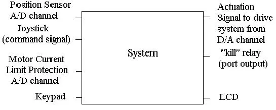
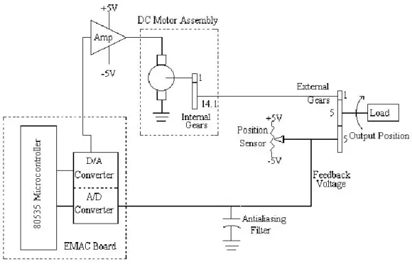
Figure 2 presents a more detailed block diagram of the system, encompassing several components and their interactions. The core components include the microcontroller board, DC motor assembly, external gears, a position sensor (potentiometer), and an antialiasing filter.
The microcontroller board, developed by EMAC Inc. in Carbondale, IL, comprises a keypad, an LCD display, A/D and D/A converters, and the 80535 microcontroller. It offers 24 bits of digital I/O, 4 counters/timers, and 10 external interrupts.
The D/A converter output drives an external power amplifier, which operates in a voltage-follower configuration. This amplifier can deliver a maximum of 3 Amps to the DC motor. The DC motor, in turn, transforms the control voltage into mechanical position and velocity, facilitating movement in the robot arm.
To reduce the motor rotor velocity and increase torque, external gears with a 70.5 reduction are employed. This setup allows the motor to encounter a smaller load, providing torque advantages.
A potentiometer serves as the position sensor, with its pot arm connected to the robot arm via a 1:1 gear. The potentiometer is supplied with +/- 5 volts, where the arm’s zero-degree position corresponds to zero volts. An antialiasing filter, represented by a capacitor, is employed to filter the feedback voltage from the potentiometer, removing power supply noise. The combination of the potentiometer resistance and the capacitor forms a low-pass filter.
The power amplifier, DC motor, gear train, potentiometer, and antialiasing filter are part of a system manufactured by Quanser Consulting. The company also provides test software and simple controller software for their system, enabling seamless integration and operation.
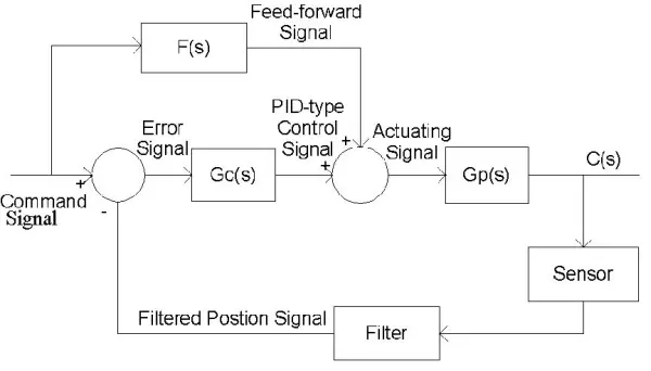
We also need to assess and examine some internal signals that play a crucial role in the evaluation and testing process. The D/A converter output channels will provide access to the following signals, as depicted in the control block diagram shown in Figure 3:
1. Command signal: Represents the desired position of the robot arm, acting as a reference for the control system.
2. Feed-forward signal: Signifies the output signal generated by the feed-forward compensator, contributing to the overall control strategy.
3. PID-type controller signal: Reflects the output signal produced by the PID (proportional+integral+derivative)-type controller, a key component of the control system.
4. Filtered position signal: Corresponds to the actual position sensor signal after undergoing filtering for noise reduction and accuracy improvement.
5. Actuating signal: This signal is responsible for driving the robot arm system and is directly connected to the power amplifier, enabling effective actuation and control of the system.
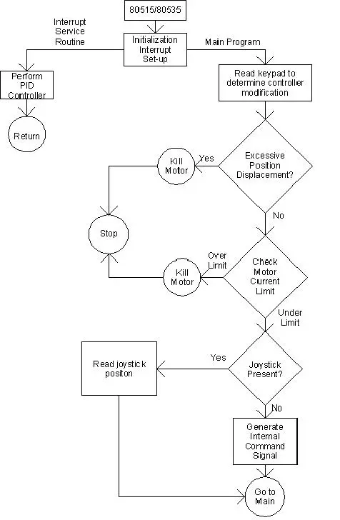
The software flowchart, as depicted in Figure 4, encompasses both an interrupt service routine and the main program. The software includes mechanisms to deactivate the motor in case of excessive position displacement or when the current surpasses its designated limit. Additionally, it checks for the presence of the joystick. Timer 2 of the 80535 microcontroller will be utilized to generate interrupts for performing PID controller calculations. Initially, the timer will be configured for a 5-millisecond interrupt, resulting in a 200 Hz sampling rate. This rapid sampling interval will make the overall system behave as if it were a continuous-time system rather than a discrete-time system. In the future, the interrupt time will be further reduced, but this aspect will not be addressed until the second semester of senior year during the course “EE432 Control Theory II”. Based on previous research, Dr. Dempsey recommended the 200 Hz sampling rate.
For our project, rather than conducting a patent search, we decided to explore various microcontroller boards suitable for the control system. The minimum requirements for the microcontroller board included an INTEL microcontroller, 4 channels of analog-to-digital converters, 4 channels of digital-to-analog converters, external RAM for user programs, the ability to download programs from a personal computer (PC), a keypad, and an LCD for displaying status information. After careful evaluation, the EMAC board was deemed suitable for our senior project, and it was selected by our advisor, Dr. Dempsey. Other manufacturers, such as Advanced Education Systems (AES) and Rigel Corporation, were also considered during the evaluation process. Extensive web research, which took over twenty hours, was conducted to find the appropriate vendor, and the EMAC board stood out due to its hardware features, such as an external keypad and a 2-line LCD. While the debugging software system provided with the EMAC board was found to be lacking, the same was true for the other vendors’ offerings. To address this, part of our senior project time will be devoted to exploring a professional debugging package that can work seamlessly with the EMAC board.
Regarding standards, since the EMAC board will be used in a standalone manner, there are no specific standards that directly apply to the project. However, during the development phase, the EMAC board will connect to an IBM compatible computer. The relevant standards for the computer are listed in Table 1:
1. IBM 486 compatible computer or higher with a math co-processor.
2. DOS version 6.2.
3. Windows 3.11 or WIN95.
4. At least 1 COM port compliant with RS232 standards.
Datasheet
The input signal to the control system is depicted in Figure 5. The set points, represented by +CMD and -CMD, indicate the desired final positions. The slope of the waveform represents the velocity. In this case, a velocity command of 100 degrees per second (?/sec) is illustrated in the figure.
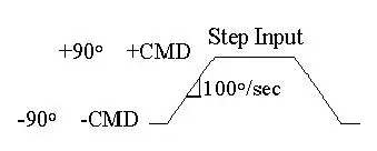
The numerical specifications for the input signal shown above are listed in Table 2.
TABLE 2:
Numerical Specifications for Step Input
1. | CMD | <= 90 degree
2. Velocity(max) = 45%/sec.
The control system’s outputs consist of the robot arm’s position and velocity. To measure the numerical specifications listed in Table 3, we will use a Tektronix TDS 340A Oscilloscope. However, due to the low frequencies involved (under 1 Hz), measuring these specifications can be time-consuming, taking hours.
To reduce measurement time, we will focus on the less time-consuming measurements such as % O.S. (percent overshoot), Ts (settling time), and tp (peak time). The remaining measurements will require finding the Bode plot of the system, which can also be a time-consuming process taking hours.
TABLE 3:
Measured Outputs of Control System
Approximate value of Position
% O.S. – Percent overshoot = 5(%).
tp – Time to first peak = 6(s).
Ts – Settling time =9(s).
Mp – Resonant peak = 1.1.
Wp – Resonant frequency =0.16(rad/sec).
BWc.l. – Closed loop bandwidth = 0.5(rad/sec).
PM – Phase margin =69.
GM – Gain margin =4.
ess < 2 degree.
VELOCITY
Tracking error < 2 degree.
The user interface for this project comprises the keypad and the LCD. Since the LCD has only two lines available for displaying information, two modes will be used. The first mode will be for user input, which will be entered through the keypad. Table 4 provides a list of possible inputs from the user. To enter these parameters, a help menu will guide the user. For instance, pressing the keypad’s “1” button will turn the motor on, while pressing “0” will turn the motor off.
TABLE 4:
User Inputs
1. Motor ON/OFF.
2. kp gain.
3. Command set point.
4. Ramp velocity.
5. Command frequency.
The LCD’s second mode will display the signals illustrated in Figure 3. The user can choose which signal to display in real-time from a help menu, providing a valuable tool for system evaluation and analysis.
Senior Project Demonstration
For the demonstration, we will measure and compare the percent overshoot, time to the first peak, and settling time with the simulation results obtained from MATLAB. This approach will efficiently validate the functionality of our controller. Additionally, we will employ prediction equations to calculate parameter values in the frequency domain, allowing further comparison with simulation results. The necessary equipment for conducting this demonstration is outlined in Table 5.
TABLE 5:
Equipment List
1. Tektronix TDS 340A Oscilloscope
2. Hewlett Packard 33120A Waveform Generator
- What microcontroller is used in the project?
The project uses an enhanced 8051 microcontroller, specifically the 80535. - How is user input and status displayed?
User input is via an add-on keypad and status is displayed on a 2-line LCD on the EMAC board. - Does the system include motor safety features?
Yes, the system incorporates motor current limit protection and motor disable hardware/software to prevent excessive position displacements. - What sampling rate is used for PID calculations?
Timer 2 is configured to generate interrupts at 5 milliseconds, yielding a 200 Hz sampling rate for PID calculations. - What signals are available from the D/A outputs for testing?
The D/A channels provide command signal, feed-forward signal, PID-type controller signal, filtered position signal, and actuating signal. - What position sensor and filtering are used?
A potentiometer with a 1:1 gear to the arm provides position; an antialiasing capacitor with the pot forms a low-pass filter. - Which board was chosen and why?
The EMAC board was chosen because it met minimum requirements (INTEL microcontroller, A/D and D/A channels, external RAM, PC download capability, keypad, and LCD) and had suitable hardware features. - What measurements will be taken during the demonstration?
The demonstration will measure percent overshoot, time to first peak, and settling time and compare them to MATLAB simulations. - What external system provides the motor, amplifier, and sensors?
Quanser Consulting supplies the power amplifier, DC motor, gear train, potentiometer, antialiasing filter, test software, and simple controller software. - What computer and OS standards are required for development?
An IBM 486 compatible or higher with math coprocessor, DOS 6.2, Windows 3.11 or WIN95, and at least one RS232 COM port are listed as relevant standards for the connected PC.