8051 MICROCONTROLLER

8051 Microcontroller based electronic locker system

CIRCUIT DESCRIPTION

Security is a prime concern in our day-today life. Everyone wants to be as much secure as possible.The issue of security is very paramount at home doors and safe. An access control for doors formsvital.link
in a security chain. Therefore we intend to aid in security at home by bringing in an electronic code lock system that involves an individual to enter the password before getting an access to some items, a particular room or building.This code lock system is not just the normal single user code lock system that required a user to insert an already programmed code to gain access to a room or safe; it is a code lock system that has password and enable multiple user access.

The microcontroller based Door locker is an access control system that allows only authorized persons to access a restricted area. The system is fully controlled by the 8 bit microcontroller AT89C2051 which has a 2Kbytes of ROM for the program memory. The system has a Keypad by which the password can be entered through it. When the entered password equals with the password stored in the memory then the door is opened. If we entered a wrong password for more than three times then the Alarm is switched on.

The data pins of LCD are connected to P1 port & RS,R/W,E pins are connected to P0.2,P0.3,P0.4. L293D is used to rotate motor bidirectionaly to open & close the locker. A 4*3 keypad is used to enter the numbers 0 to 9 & ‘*’, ‘#’. There is a system menu, contains three buttons for open locker, reset password & close the locker.
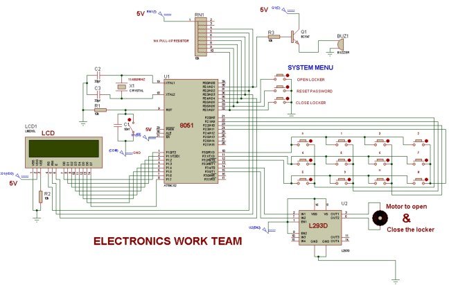
 8051 MICROCONTROLLER

PROJECT CODE

#include< reg51.h >
#define col P2
#define row P3

sbit m1=P3^4;
sbit m2=P3^5;
sbit bu=P0^1;
sbit rs=P0^2;
sbit rw=P0^3;
sbit en=P0^4;
sbit start=P0^5;
sbit rst=P0^6;
sbit mp=P0^7;
sfr lcddata=0x90;

void delay(int a)
{
int i,j;
for(i=0;i<a;i++) for(j=”0;j<1100;j++);” }=”” void=”” command(unsigned=”” char=”” s)=”” initialise=”” of=”” the=”” lcd=”” {=”” lcddata=”s;” rs=”0;” rw=”0;” en=”1;” delay(5);=”” lcddisplaydata(unsigned=”” data=”” writing=”” delay(8);=”” displaydata(unsigned=”” *word)=”” int=”” x;=”” for(x=”0;word[x]!=0;x++)” lcddisplaydata(word[x]);=”” unsigned=”” array[3][4]=”{‘0′,’1′,’2′,’3’,” ‘4’,’5′,’6′,’7′,=”” ‘8’,’9′,’*’,’#’};=”” n=”0;” m=”0;” i,p,q,r;=”” main()=”” colloc,=”” rowloc;=”” array1[4];=”” array2[4]=”{‘3′,’1′,’1′,’2’};” array3[4];=”” locker1:=”” col=”0xFF;” row=”0x00;” m1=”0;” m2=”0;” bu=”0;” mp=”1;” p=”0;” q=”0;” r=”0;” start=”1;” rst=”1;” command(0x01);=”” command(0x38);=”” command(0x0c);=”” command(0x84);=”” displaydata(“press=”” key”);=”” command(0xc0);=”” displaydata(“from=”” system=”” menu”);=”” while(1)=”” if(start=”=0)” goto=”” locker2;=”” else=”” if(rst=”=0)” locker3;=”” locker2:=”” command(0x82);=”” delay(10);=”” displaydata(“enter=”” your”);=”” command(0xc3);=”” displaydata(“password”);=”” delay(80);=”” command(0x80);=”” locker5;=”” locker3:=”” current”);=”” command(0xc4);=”” locker4:=”” command(0x83);=”” new”);=”” displaydata(”=”” password”);=”” locker5:=”” do=”” colloc=”col;” &=”0x0f;” }while(colloc!=”0x0f);” }while(colloc=”=0x0f);” if(colloc!=”0x0f)” rowloc=”0;” break;=”” if(p=”=1)” if(colloc=”=0x0E)” array1[n]=”array[rowloc][0];” n++;=”” locker6;=”” if(q=”=1)” locker7;=”” if(r=”=2)” locker11;=”” array2[n]=”array[rowloc][0];” locker9;=”” array3[n]=”array[rowloc][0];” locker8;=”” locker6:=”” if(n<4)=”” lcddisplaydata(‘*’);=”” if(n=”=4)” delay(50);=”” if(array1[1]=”=array2[1]&&array1[2]==array2[2]&&array1[3]==array2[3]&&array1[0]==array2[0])” displaydata(“right=”” locker14;=”” displaydata(“wrong=”” locker15;=”” locker7:=”” locker4;=”” locker12;=”” locker8:=”” if(array3[1]=”=array2[1]&&array3[2]==array2[2]&&array3[3]==array2[3]&&array3[0]==array2[0])” displaydata(“new=”” password=”” has”);=”” displaydata(“been=”” set”);=”” delay(100);=”” locker1;=”” locker13;=”” locker9:=”” locker10;=”” locker10:=”” displaydata(“conform=”” locker11:=”” locker16;=”” locker12:=”” m++;=”” if(m<3)=”” delay(500);=”” locker13:=”” locker14:=”” delay(125);=”” while(mp!=”0);” locker15:=”” locker16:=”” <=””>

DESCRIPTION

This post is related to basic operation of 8051 microcontroller with LEDs. LEDs are connected with P2 port & 6 switches are connected with P1 port of 8051. By pressing different switches, LEDs will glow in different manners. This post may be very helpful for 8051 microcontroller beginners.

CODE

#include < reg51.h >

sbit switch1=P1^0;
sbit switch2=P1^1;
sbit switch3=P1^2;
sbit switch4=P1^3;
sbit switch5=P1^4;
sbit switch6=P1^5;

int i,j,l;
int n=7;

void delay(int k) //This function produces a delay in msec.
{
for(i=0;i<k;i++) {=”” for(j=”0;j<1275;j++);” }=”” int=”” arr[8]=”{0xFE,0xFD,0x0FB,0xF7,0xEF,0xDF,0xBF,0x7F};” void=”” main()=”” p2=”0xFF;” p1=”0xFF;” if(switch1=”=0)” for(l=”0;l<8;l++)” delay(50);=”” if(switch2=”=0)”>=0;l–)
{
P2=arr[l];
delay(50);
}
}

if(switch3==0)
{
P2=0x7E;
delay(50);
P2=0xBD;
delay(50);
P2=0xDB;
delay(50);
P2=0xE7;
delay(50);
}

if(switch4==0)
{
P2=0xE7;
delay(50);
P2=0xDB;
delay(50);
P2=0xBD;
delay(50);
P2=0x7E;
delay(50);
}

if(switch5==0)
{
P2=0xAA;
delay(50);
P2=0x55;
delay(50);
}

if(switch6==0)
{
P2=0x00;
delay(50);
P2=0xFF;
delay(50);
}

}

Microcontroller 8051 Piano in Keil and Proteus simulator

DISCRIPTION:-

The piano is a musical instrument played mainly by means of a keyboard. It is one of the most popular instruments in the world.

Today, it is one of the two parts of Indian classical music, with the other one being Carnatic music, which represents the music of South India.

he rhythmic organization is based on rhythmic patterns called Taal. The melodic foundations are called ragas. One possible classification of ragas is into “melodic modes” or “parent scales”, known as Thaats, under which most ragas can be classified based on the notes they use.
Thaats may consist of up to seven scale degrees, or swara. Hindustani musicians name these pitches using a system called Sargam, the equivalent of Western movable do solfege:
Sa (Shadaj) = Do
Re (Rishab) = Re
Ga (Gandhar) = Mi
Ma (Madhyam) = Fa
Pa (Pancham) = So
Dha (Dhaivat) = La
Ni (Nishad) = Ti
Sa (Shadaj) = Do
Both systems repeat at the octave. The difference between sargam and solfege is that re, ga, ma, dha, and ni can refer to either “Natural” (Shuddha) or altered “Flat” (Komal) or “Sharp” (Tivra) versions of their respective scale degrees. As with movable do solfege, the notes are heard relative to an arbitrary tonic that varies from performance to performance, rather than to fixed frequencies, as on a xylophone. The fine intonational differences between different instances of the same swara are called shrutis. The three primary registers of Indian classical music are Mandra (lower), Madhya (middle) and Taar (upper). Since the octave location is not fixed, it is also possible to use provenances in mid-register (such as Mandra-Madhya or Madhya-Taar) for certain ragas. A typical rendition of Hindustani raga involves two stages:

In this project we are generating the same friquencies whch are excately same as sa re ga ma pa dha ni sa by using the controller

CODE:-

#include<reg51.h>
sbit bu=P2^0;

void delay1on()
{
TMOD=0X01;
TH0=0Xf8;
TL0=0X80;
TR0=1;
while(TF0==0);
TR0=0;
TF0=0;
}

void delay2on()
{
TMOD=0X01;
TH0=0Xf9;
TL0=0X55;
TR0=1;
while(TF0==0);
TR0=0;
TF0=0;
}

void delay3on()
{
TMOD=0X01;
TH0=0Xfa;
TL0=0X00;
TR0=1;
while(TF0==0);
TR0=0;
TF0=0;
}

void delay4on()
{
TMOD=0X01;
TH0=0Xfa;
TL0=0Xab;
TR0=1;
while(TF0==0);
TR0=0;
TF0=0;
}

void delay5on()
{
TMOD=0X01;
TH0=0XFB;
TL0=0X00;
TR0=1;
while(TF0==0);
TR0=0;
TF0=0;
}

void delay6on()
{
TMOD=0X01;
TH0=0XFB;
TL0=0X80;
TR0=1;
while(TF0==0);
TR0=0;
TF0=0;
}

void delay7on()
{
TMOD=0X01;
TH0=0XFC;
TL0=0X00;
TR0=1;
while(TF0==0);
TR0=0;
TF0=0;
}
void delay8on()
{
TMOD=0X01;
TH0=0XFC;
TL0=0X40;
TR0=1;
while(TF0==0);
TR0=0;
TF0=0;
}

void main()
{

P2=0X00;
while(1)
{

if(P1==0xFE)
{
bu=~bu;
delay1on();

}
else if(P1==0xFD)
{
bu=~bu;
delay2on();
}
else if(P1==0XFB)
{
bu=~bu;
delay3on();

}
else if(P1==0XF7)
{
bu=~bu;
delay4on();

}
else if(P1==0XEF)
{
bu=~bu;
delay5on();

}
else if(P1==0XDF)
{
bu=~bu;
delay6on();

}
else if(P1==0XBF)
{
bu=~bu;
delay7on();

}
else if(P1==0X7F)
{
bu=~bu;
delay8on();

}
}
}


VEDIO:-8051 MICROCONTROLLER schematic

8051 Microcontroller based Pendulam operation

DISCRIPTION:-

In this Project Multi-Pattern Running light is used to generate several designs of Running Lights. We use ten LED’s for display. The designs can be selected by using switches UP and DOWN. The 8 bit Microcontroller is used to control all the operations. It control the LED’s though the Ports.

The above system is monitored and controlled by the 8 bit microcontroller 8051. The Microcontroller continuously monitors the Switches and switch on/off the LED’s according to the Program. The Power for the circuit is derived from the Step down transformer and the 5V regulator IC7805. The regulator IC produces a constant 5v output.

CODE:-

#include<reg51.h>

/**********************STARTING OF PROGRAM FUNCTION************************************************/

//_______________________DELAY SUBROUTINE_________________________________________________/

void delay(int a)
{
int i,j;
for(i=0;i<a;i++)
for(j=0;j<1275;j++);                          //CREATING DELAY BY INSTRUCTION
}

/***************************MAIN PROGRAM*********************************************************/
void main()
{
int k;
start:                     //P1 PORT AS OUTPUT PORT,WITH VARIABLE K & SHIFT THE POSITION OF LED AMONG 8 PIN OF P1
while(1)
{
//______________ CODE FOR SHIFTING(LED GLOWING) IN DECREMENT ORDER ONE BY ONE ___________/

for(k=0x80;k>=0x01;k>>=1)     //LOOP FOR SHIFTING FROM 1-POSITION to LAST POSITION IN FORWARD

DIRECTION

{
P1=~k;                                                                            //LED GLOW AT P1 PORT FOR CORRESPONDIG POSITION OF K
delay(50);
if(k==0x01)                                     //CONDITION,WHEN LAST POSITION OCCUR DURING TRAVELLING IN FORWARD

DIRECTION
{
for(k=0x01;k<=0x40;k<<=1)                                                   //LOOP FOR SHIFTING IN REVERSE DIRECTION, FROM LAST

POSITION TO 2-POSITION
{
P1=~k;
delay(50);                                                                  //CALLING DELAY SUBROUTINE
if(k==0x40)                                                             //CONDITION,WHEN 2-POSITION OCCUR DURING TRAVELLING IN

REVERSE DIRECTION
{
for(k=0x40;k>=0x02;k>>=1)                                                  //LOOP FOR SHIFTING IN FORWARD DIRECTION, FROM 2-

POSITION TO 2nd LAST POSITION
{
P1=~k;
delay(50);
if(k==0x02)                                                               //CONDITION,WHEN 2nd LAST POSITION OCCUR DURING TRAVELLING IN

FORWARD DIRECTION
{
for(k=0x02;k<=0x20;k<<=1)                                                 //LOOP FOR SHIFTING IN REVERSE DIRECTION,FROM 2nd LAST

POSITION TO 3rd POSITION
{
P1=~k;
delay(50);
if(k==0x20)                                                                                     //CONDITION WHEN 3rd POSITION OCCUR DURING

TRAVELLING IN REVERSE DIRECTION
{
for(k=0x20;k>=0x04;k>>=1)                                                   //LOOP FOR SHIFTING IN FORWARD DIRECTION,FROM 3rd

POSITION TO 6th POSITION
{
P1=~k;
delay(50);
if(k==0x04)                                                                                             //CONDITION,WHEN 6th POSITION OCCUR DURING

TRAVELLING IN FORWARD DIRECTION
{
for(k=0x04;k<=0x10;k<<=1)                                                     //LOOP FOR SHIFTING IN REVERSE DIRECTION,FROM 6th

POSITION TO 4th POSITION
{
P1=~k;
delay(50);
if(k==0x10)                                                                                    //CONDITION WHEN 4th POSITION OCCUR DURING TRAVELLING

IN REVERSE DIRECTION
{
for(k=0x10;k>=0x08;k>>=1)                                                           //LOOP FOR SHIFTING IN FORWARD DIRECTION,FROM 4th

POSITION TO 5th POSITION
{
P1=~k;
delay(50);
if(k==0x08)                                                                                      //CONDITION,WHEN 5th POSITION OCCUR DURING

TRAVELLING IN FORWARD DIRECTION
{

/********CODE FOR SHIFTING(LED GLOWING) IN INCREMENT ORDER ONE BY ONE******************************/

for(k=0x08;k<=0x10;k<<=1)                                                           //LOOP FOR IN REVERSE DIRECTION,FROM 5th POSITION

TO 4th POSITION
{
P1=~k;
delay(50);
if(k==0x10)                                  //CONDITION,WHEN 4th POSITION DURING TRAVELLING IN REVERSE DIRECTION
{
for(k=0x10;k>=0x04;k>>=1)                                        //LOOP FOR SHIFTING IN FORWARD DIRECTION,FROM 4th

POSITION TO 6th POSITION
{
P1=~k;
delay(50);
if(k==0x04)                      //CONDITION,WHEN 6th POSITION OCCUR DURING TRAVELLING IN FORWARD DIRECTION
{
for(k=0x04;k<=0x20;k<<=1)                           //LOOP FOR SHIFTING IN REVERSE,FROM 6th POSITION TO 3rd POSITION
{
P1=~k;
delay(50);
if(k==0x20)                           //CONDITION,WHEN 3rd POSITION OCCUR DURING TRAVELLING IN REVERSE DIRECTION
{
for(k=0x20;k>=0x02;k>>=1)                          //LOOP FOR SHIFTING IN FORWARD,FORM 3rd POSITION TO 7th POSITION
{
P1=~k;
delay(50);
if(k==0x02)                             //CONDITION,WHEN 7th POSITION OCCUR DURING TRAVELLING IN FORWARD DIRECTION
{
for(k=0x02;k<=0x40;k<<=1)                             //LOOP FOR SHIFTING IN REVERSE,FROM 7th POSITION TO 2nd POSITION
{
P1=~k;
delay(50);
if(k==0x40)                              //CONDITION,WHEN 2nd POSITION OCCUR DURING TRAVELLING IN REVERSE DIRECTION
{
for(k=0x40;k>=0x01;k>>=1)                         //LOOP FOR SHIFTING IN FORWARD,FROM 2nd POSITION TO 8th POSITION
{
P1=~k;
delay(50);
if(k==0x01)                        //CONDITION,WHEN 8th POSITION OCCUR DURING TRAVELLING IN FORWARD DIRECTION
{
for(k=0x01;k<=0x80;k<<=1)                               //LOOP FOR SHIFTING IN REVERSE,FROM 8th POSITION TO 1st POSITION
{
P1=~k;
delay(50);
if(k==0x80)                               //CONDITION WHEN 1st POSITION OCCUR DURING TRAVELLING IN REVERSE DIRECTION
{
goto start;                       //CODE FOR REPEATING ALL ABOVE PROCESS FROM STARTING,SO JUMP TO “START” LEVEL
}

For more detail: 8051 MICROCONTROLLER

About The Author

Ibrar Ayyub

I am an experienced technical writer holding a Master's degree in computer science from BZU Multan, Pakistan University. With a background spanning various industries, particularly in home automation and engineering, I have honed my skills in crafting clear and concise content. Proficient in leveraging infographics and diagrams, I strive to simplify complex concepts for readers. My strength lies in thorough research and presenting information in a structured and logical format.

Follow Us:
LinkedinTwitter