Introduction
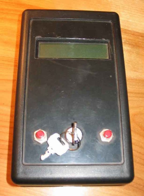
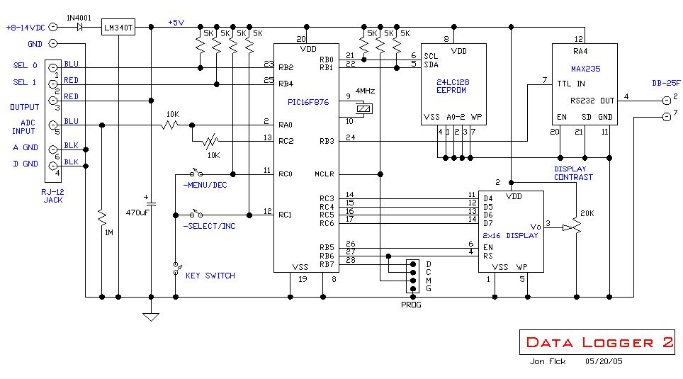
This circuit is a data logger that records voltage samples at specific time intervals.
I’ve used it to record the voltage discharge curve on NiCad battery packs. The data file can be dropped into a spreadsheet and plotted.
I’ve also used it to record the amount of time a possibly defective refrigeration unit was running during a 24-hour period (using a current clamp and full wave bridge.)
Features
- Input range: 0-5VDC and 0-14VDC.
- Capacity: 8192 samples
- Time interval is settable from 1 to 65535 seconds
- Dump to display or 9600 baud dump via RS232
- Key switch locks front panel pushbuttons during logging
Specifications
- Power: 8-12V
Operation
- Provide +8-14VDC power for the data logger. NOTE: first remove any voltage or signal that is connected to the datalogger input or it may partially power up the microprocessor even without the power applied and cause it to come up in an unknown state.
- Set up the source of voltage you will be logging. For instance, if you are using a clamp-on current transformer (Fluke and others) to monitor the current used by a motor, you must convert the AC output to DC using a bridge rectifier and small capacitor such as 0.1µF. An appropriate parallel resistor will allow you to scale the DC voltages to a meaningful and proportionate value between 0 and 5 volts. Or, if you are measuring temperature using a thermister and resistor, connect the thermister/resistor between the +5V AUX OUTPUT and GND jacks, and connect the center to the ADC input jack.
- Generally speaking, the MENU/DEC switch cycles through various menu options and the SELECT/INC switch selects an option. The buttons auto-repeat approximately two times per second. The options are:
- START – start data logging
- STOP – stop logging
- STATUS – display the time interval and sample count
- RESET – reset the sample count to zero
- INTERVAL – set the time interval (1-65535 seconds)
- RANGE – set the voltage range to 5V or 14V
- VIEW – view the data samples
- DUMP – send the data samples out RS232 at 9600 baud
Code:
/*********************************************************************************
DATALOG5.C

With interrupt button on dump routine (both buttons pressed.)

This is a data logger.  It has a 5V and 14V ADC input and collects (with
the 24LC128 EEPROM memory) 8192 samples.  Control and display is done
via two pushbuttons and and LCD display.  Data dump can be viewed on
the display or sent to a terminal via 9600 baud RS232.

WORKING CODE

                       ---------              ---------
               +5--20-|Vdd    B0|-----21->-6-|SCL*     |    *Pullups required
               +5---1-|Mclr   B1|-----22->-5-|SDA*     |     on SCL and SDA.
              Gnd---8-|Vss      |            | 24LC128 |
              Gnd--19-|Vss      |       +5-8-|Vdd      |
             4MHz--10-|Xtal     |      Gnd-4-|Vss      |           --------
                 ---9-|Xtal     |      Gnd-7-|Wp       |   Gnd-20-|EN      |
                      |         |      Gnd-1-|A0       |   Gnd-21-|SD      |
                      | 16F876  |      Gnd-2-|A1       |   Gnd-11-|Vss     |
                      |         |      Gnd-3-|A2       |    +5-12-|Vcc     |
              POT     |         |             ---------           |        |
            ©-10K--13-|C2       |                                 |        |
    In--10K-*-------2-|A0     B3|-24-->----9600 baud------------7-|IN   OUT|-4-->-Tx
                      |         |                                 |        |
       -Menu/Dec --11-|C0       |                                 | MAX235 |
     -Select/Inc --12-|C1       |                                  --------
                      |         |             ---------
                      |       C3|-----14--11-|D4       |
                      |       C4|-----15--12-|D5       |
                      |       C5|-----16--13-|D6       |
                      |       C6|-----17--14-|D7       |
                      |         |            |         |-3--20K pot (contrast)
                      |       B5|-----26---6-|EN       |
                      |       B6|-----27---4-|RS       |
                      |         |            |         |
                      |         |       +5-2-|         |
                      |         |      Gnd-1-|         |
                      |         |      Gnd-5-|         |
                      |         |            | DISPLAY |
                       ---------              ---------

*********************************************************************************/

#include < 16F876.H >
#device ADC=10
#include < jonsinc.h >

#fuses XT, NOPROTECT, NOPUT, NOWDT, NOBROWNOUT, NOLVP, NOCPD, NOWRT

// ADC
#define VDD                 5.00

// INTERNAL EEPROM ASSIGNMENTS
#define SAMPLE_INTERVAL_HI 0
#define SAMPLE_INTERVAL_LO 1
#define SAMPLE_COUNT_HI    2
#define SAMPLE_COUNT_LO    3
#define LOGGING_STATE      4
#define RANGE              5

// EXTERNAL EEPROM ASSIGNMENTS 128Kbit EEPROM is 16384 bytes
#define EEPROM_BYTE_SIZE   16384
#define EEPROM_SCL         PIN_B0
#define EEPROM_SDA         PIN_B1

// LCD STUFF
#define LCD_D0  PIN_C3
#define LCD_D1  PIN_C4
#define LCD_D2  PIN_C5
#define LCD_D3  PIN_C6
#define LCD_EN  PIN_B5
#define LCD_RS  PIN_B6
#define LINE_1  0x00
#define LINE_2  0x40
#define CLEAR_DISP  0x01

#define MENU_DEC_SWITCH        PIN_C0
#define SELECT_INC_SWITCH      PIN_C1
#define RANGE_SHUNT            PIN_C2
#define SEL0                   PIN_B2
#define SEL1                   PIN_B4

#define MINIMUM_INTERVAL   1
#define STATE_START        0
#define STATE_STOP         1
#define STATE_STATUS       2
#define STATE_RESET        3
#define STATE_RANGE        4
#define STATE_INTERVAL     5
#define STATE_VIEW         6
#define STATE_DUMP         7
#define MAX_MENU_STATE     7

#define hi(x)  (*(&x+1))

#use delay ( clock=4000000 )
#use standard_io ( A )
#use standard_io ( B )
#use standard_io ( C )
#use rs232 ( baud=9600, xmit=PIN_B3 )
#use i2c ( master, scl=EEPROM_SCL, sda=EEPROM_SDA )

void PrintMenu ( void );       // protos
void init_ext_eeprom ( void );
void write_ext_eeprom ( long int lngAddress, BYTE intData );
BYTE read_ext_eeprom ( long int lngAddress );
void SetTime ( void );
void CheckSample ( void );
void CheckSwitches ( void );
char GetEchoNumChar ( void );
void LCD_Init ( void );
void LCD_SetPosition ( unsigned int cX );
void LCD_PutChar ( unsigned int cX );
void LCD_PutCmd ( unsigned int cX );
void LCD_PulseEnable ( void );
void LCD_SetData ( unsigned int cX );
void DisplayVolts ( long iAdcValue, char cLoc );
float ScaleAdc ( long iValue );
void SetRange ( BYTE cDisplay );

static long iIntervalCount, iIntervalTrigger, iSampleCount;
static char cLogging, cSampleFlag, cLedCount;
static char cLoggingIndicatorFlag, cAdcFlag, cToggleFlag;
static char cInterruptCount, cViewing;
static char cMenuState, cSelectFlag, cRange;
static char cMenuDecSwitchOn, cMenuSwitchCount;
static char cSelIncSwitchOn, cSelectSwitchCount;

//****************************************************************************
For more detail: DATA LOGGER measures and stores voltage using PIC16F876


