


Summary of 6 Digits LED 7-Segment Multiplexing using PIC16F627A
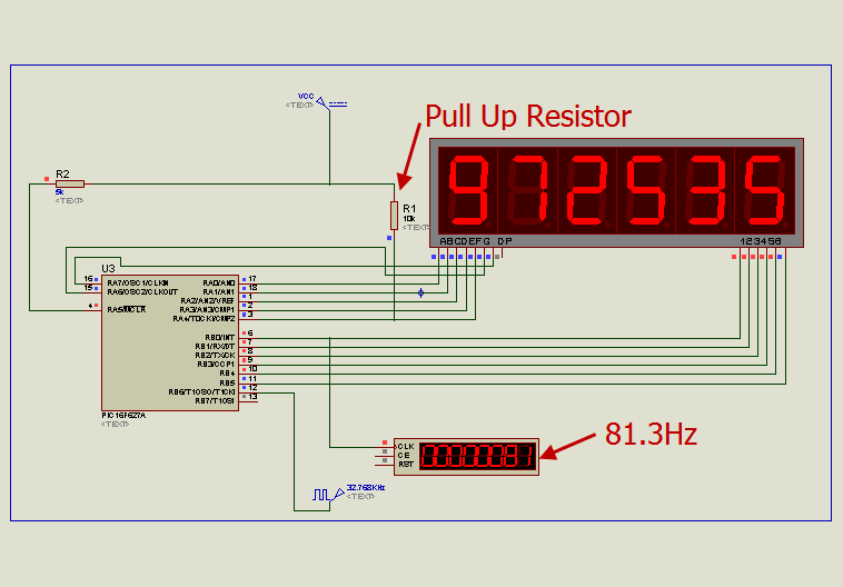
Summary: This project implements a 6-digit 7-segment LED multiplexed counter (up to 999999 seconds) using a PIC16F627A/628 microcontroller. Timer0 handles digit scanning at an ~81.3 Hz refresh (4 MHz internal oscillator, 1:8 prescaler). Timer1 produces 1-second ticks to increment the six-digit BCD-like counters. RA4 uses a 10 kΩ pull-up because it is open-drain. The code is written in MikroC and uses interrupts for TMR0 and TMR1 to drive multiplexing and timekeeping.Parts used in the 6 Digits LED 7-Segment Multiplexing project:
- PIC16F627A or PIC16F628 microcontroller
- 6 × LED 7-segment displays
- 32.768 kHz crystal
- 10 kΩ pull-up resistor for RA4
- Power supply (appropriate for PIC and LEDs)
- Wiring/PCB or breadboard for connections
In the post 'LED 7-Segment Multiplexing', I have explained about the concept and benefits of multiplexing. Multiplexing implementation is very similar to driving Led Dot Matrix. I use Timer0 interrupt for switching through each digit. Timer0 or TMR0 is an 8-bit timer which overflows every 256 (0xFF) counts. It's known that the refresh rate above 50Hz would be enough for human's eyes to see the display without recognizing the flickering. If I set TMR0 with 1:8 Prescaler, the multiplexing frequency will be
4MHz(internal OSC.)/4(working OSC)/8(prescaler)/256(max counts of TMR0)/6(number of digits) = 81.3 Hz which is good for a display.Just an example, I have implemented (in Proteus) a 999999-second counter by using 6 Digits LED 7-Segment Multiplexing technique. There are 2 main components in the project, PIC16F627A or PIC16F628 and 6 x LED7-segment display. The schematic shows below. The crystal is 32.768KHz as usual. There is a 10KOhm pull up resistor at RA4 pin as this pin is an open-drain pin as I described in "Open-Drain RA4 pin on PIC Microcontroller".
The source code in MikroC is listed below: (.hex is also available, please feel free to contact me)
//PIC16F627A
//4MHz Internal OSC
//MUX by the MUC itself with Interrupt
//TMR0 .. check the prescelar+delay in scan routine as they are related
//[email protected]
unsigned short number [10] = {
0x5F, 0x06, 0x9b, 0x8f, 0xC6, 0xCd, 0xDD, 0x07,
0xDf, 0xCf
};
unsigned short digit [6];
unsigned short counter;
unsigned short shift_register;
unsigned short x1;
unsigned short x2;
unsigned short x3;
unsigned short x4;
unsigned short x5;
unsigned short x6;
unsigned short tick;
void interrupt ()
{
    if (INTCON.T0IF)
    {
        //Scan digits with TMR0
        INTCON.T0IF = 0;
        if (counter == 5)
        {
            PORTA = number [digit [counter]];
            Delay_us (500);
            shift_register = 0x01;
            PORTB = ~shift_register;
            PORTA = 0x00;
            counter = 0;
        } else
        {
            PORTA = number [digit [counter]];
            Delay_us (500);
            shift_register = shift_register << 1;
            PORTB = ~shift_register;
            PORTA = 0x00;
            counter ++;
        }
    }
    if (PIR1.TMR1IF)
    {
        TMR1H = 0x80;
        PIR1.TMR1IF = 0;
        tick = 1;
        //update current time
        x6 ++;
        if (x6 > 9)
        {
            x6 = 0;
            x5 ++;
            if (x5 > 9)
            {
                x5 = 0;
                x4 ++;
                if (x4 > 9)
                {
                    x4 = 0;
                    x3 ++;
                    if (x3 > 9)
                    {
                        x3 = 0;
                        x2 ++;
                        if (x2 > 9)
                        {
                            x2 = 0;
                            x1 ++;
                            if (x1 > 9)
                            {
                                x1 = 0;
                            }
                        }
                    }
                }
            }
        }
    }
}
void main ()
{
    //Digital I/O for PORTA
    CMCON = 0x07;
    TRISA = 0x00;
    PORTA = 0x00;
    TRISB = 0x00;
    PORTB = 0x00;
    //Internal Clock 4MHz
    PCON.OSCF = 1;
    counter = 0;
    // Enable TMR0
    OPTION_REG.T0CS = 0;
    // Enable Prescaler
    OPTION_REG.PSA = 0;
    // PS0,1,2 = 010 = 3
    // 3 means 1:8 prescaler
    // 1:2, 1:4, 1:8, 1:16, 1:32, 1:64, 1:128, 1:256
    OPTION_REG.PS2 = 0;
    OPTION_REG.PS1 = 1;
    OPTION_REG.PS0 = 0;
    INTCON.T0IF = 0;
    INTCON.T0IE = 1;
    INTCON.GIE = 1;
    INTCON.PEIE = 1;
    T1CON = 0x0F;
    TMR1H = 0x80;
    TMR1L = 0x00;
    // Enable TMR1 interrupt
    PIE1.TMR1IE = 1;
    shift_register = 0x01;
    x1 = 0;
    x2 = 0;
    x3 = 0;
    x4 = 0;
    x5 = 0;
    x6 = 0;
    while (1)
    {
        if (tick)
        {
            tick = 0;
            //update digits
            digit [0] = x1;
            digit [1] = x2;
            digit [2] = x3;
            digit [3] = x4;
            digit [4] = x5;
            digit [5] = x6;
        }
    }
}
Source : 6 Digits LED 7-Segment Multiplexing using PIC16F627A
Quick Solutions to Questions related to 6 Digits LED 7-Segment Multiplexing:
- What microcontroller is used in the project?
The project uses PIC16F627A or PIC16F628. - How many 7-segment displays are used?
The project uses six LED 7-segment displays. - How is multiplexing implemented?
Multiplexing is implemented using Timer0 interrupt to scan each digit. - What refresh rate is achieved for the display?
With 4 MHz internal OSC and 1:8 prescaler, the multiplexing frequency is about 81.3 Hz. - What timer creates the 1-second tick for counting?
Timer1 interrupt is used to create the tick that increments the counter digits. - Why is there a pull-up resistor on RA4?
RA4 is an open-drain pin, so a 10 kΩ pull-up resistor is used on RA4. - What oscillator or clock source is shown in the schematic?
The schematic shows a 32.768 kHz crystal as usual. - What language is the source code written in?
The source code is written in MikroC.
Related projects
DHT11 Low Cost Humidity Sensor using PIC16F628A with Proteus Simulation
IntroductionThis microcontroller project demonstrates how to interface a low-cost DHT11 temperature and humidity sensor with a PIC16F628A using a Proteus simulation environment.The...
LCD & Display Projects · PIC16F628AFrequency Counter by PIC16F628
In this project we are building a basic and low cost frequency counter circuit . It can measure from 16Hz to 100Hz...
Games, Toys & Calculators · PIC16F628ATIC TAC TOE game using PIC16F628
This project is not to introduce Tic Tac Toe. Everyone knows this game. It's to introduce two features. Bi-coloured LEDs, microcontrollers and...
LED ProjectsAn Application-Driven Microcontroller Curriculum
Understanding how to apply microcontrollers lies at the core of modern embedded systems education. This student project takes an experiential approach to...
LED ProjectsBuild this microcontroller controlled rainbow flying disc – and then throw it!
Hello all and welcome to this super simple and inexpensive instructable. If you like throwing frisbees AND you like flashing lights AND...
LED ProjectsLED Scrolling Display Project Working With Circuit Diagram
We normally use a simple static LED display screen to convey a message. Earlier, when we want to display large data, we...

Ibrar Ayyub
I am an experienced technical writer holding a Master's degree in computer science from BZU Multan, Pakistan University. With a background spanning various industries, particularly in home automation and engineering, I have honed my skills in crafting clear and concise content. Proficient in leveraging infographics and diagrams, I strive to simplify complex concepts for readers. My strength lies in thorough...