Parallel interfacing LCD with MCU at least need 6 I/O pins (4 bit mode) and maximun can up to
11 I/O pins (8 bit mode). The I/O pin can be cut down to 3 pin by serial iterfacing using shift
register. They were few shift register can be used such as 74HC164, 74HC595, CD4094 and any
compatible 8 bit shift register. Before you attempt to do serial interfacing, it is good
pratice to familiar with parallel interfacing. You can find many reference from internet.
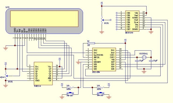
Following diagram show the serial interfacing Hitachi compatible 2 X 16 LCD modules with
Pic16F84 or Pic16F628 MCU.
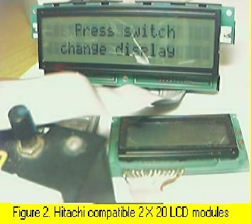
The Hitachi compatible 2 X 16 LCD modules drive by Pic16F84 MCU show on figure 1. The Hitachi compatible 2 X 20 LCD modules (optrex) drive by Pic16F84 MCU show on figure 2. When using this optrex 2 X 20 LCD modules, the Vref (pin 3 at LCD) need around -4.5v to -5.5V supply. The source code/hex file for Pic16f84 download here: F84SLCD.zip. The source code/hex file for Pic16f628 download here: 628SLCD.zip.
 More LCD reference can find here:
2. Software SPI interfacing ADC with Pic16F84/Pic16F628
Communication with the MCP3028 ADC chip is done using a simple serial interface compatible
with the SPI protocol. The Pic16f84 or Pic16f628 didn't had hardware SPI peripheral. However,
software implemeted SPI protocol can be done to communicate with 12 bit MCP3028 ADC device.
The example of this communication shown as following circuit diagram. The ADC result shown
on LCD with hex value (conversion from binary code). Press the push button (pin 6, RB0/INT)
to select the ADC channel (8 channel from CH0 to CH7). Then, connect the potention meter to
the channel and turn it. You will see the hex value change accordingly. The SPI communication
protocol need 4 line for interfacing. Using software implemeted SPI protocol enable
communication with more than one ADC device.
The hex file for Pic16f84 download here: F84S_L.zip.
The hex file for Pic16f628 download here: 628S_L.zip.
3. Simple multi channel digital voltmeter
The circuit diagram same as above 12 bit ADC interfacing. The only different is the source code
which the binary code has been change to ASCII code with decimen number. This need some math
fuction such as divide function and floating point. The math fuction for assembler code can
find from Microchip Website www.microchip.com. You can also find some documen of math fuction
from www.piclist.com or use C compiler such as Piclite for PIC16f8X/c8x series, cc5x c,
pacific c and so on. The following hex file are use Microchip Math Library (assembler code) for
this simple multi channel digital voltmeter device (using 16 bit for calculation). The maximum
hex value for the ADC channel is FFF equal to decimel number 4095. This will display on the LCD
as 5.11 volt.

Download hex file for Pic16F84 here: F84dec.zip.
Download hex file for Pic16F628 here: 628dec.zip.
*Tip on source code migration from Pic16f8X series to Pic16f62X series*
- If using PORTA pins as interfacing I/O, you need to define/set the I/O fuction for PIC16f628. Generally, the initial PORTA setting as following for I/O fuction: clrf PORTA movlw 0x07 ;turn comparators off and movwf CMCON ;enable pins for I/O functions Note: Ensure the above setting done at Bank 0. The above setting especially important if you want to migrate the source code from Pic16f8X series to Pic16f62X series.
- Always refer to data memory MAP (on Pic datasheet) to ensure that the general purpose register used not out of range when migrate one type of MCU to another type of MCU. As example, general purpose register for Pic16f84 was 0x00c to 0x04f (at bank 0). For Pic16f628 was 0x020 to 0x07f (at bank 0), 0x0a0 to 0x0ef (at bank 1) and 0x120 to 0x14f (at bank 2). It is better to define the address follow sequence.If out of range, you can re-define it easly.
- When Using bit 4 (RB4) of PORT B of Pic16F62X series as a output pin, ensure that the MCU not programmed at low voltage program mode (see Microchip datsheet) if not it will set as Schmitt Trigger input and independence of TRISB regeister I/O direction setting.
 Stepper motor controller
The stepper motor driver circuit shown as following
The opto-isolator are important which prevent destroy of MCU by the feeback voltage from
power transistor. Two adjust-able voltage regulator used to adjust the running voltage and
stopping/holding voltage of the stepper motor. The running voltage on by
the step pulse input which also signal to rotate the motor. The simple source
code using interrupt method to change the step sequence (one wave) download here:
F628_stepper for Pic16F628.
Simple mathematics algorithm able to drive more complicate step sequence (such as half step)
even for half_step 5phase stepper.
Another stepper motor circuit for X-Y table project click here:X-Y table project
More stepper motor information refer to:
1)www.cs.uiowa.edu
2)www.ams2000.com
5). 24 segments LED display module
The numerical LED display module was widely used in display application. The most common numerical LED display module consists of either 8 segmented or
16 segmented LED units. However, this type of display module only limited to display numerical character (0 to 9) and a few type of alphabet character.
Most of alphabet word message displayed using alphanumerical LED modules with dot matrix arrangement.
The 24 segments LED display module designed in such a way that enable it to display  alphabet (A to Z) and numerical (0 to 9) character.
This will able it to display most of word message using A to Z alphabet and numerical character when combine a few units of this module.
The display controlling method also more simple than the dot matrix type of alphanumerical LED module.
For more detail: 1. Serial interfacing LCD with Pic Microcontroller

