


Summary of PIC Musical Doorbell using PIC16F84A with Proteus Simulation
This project implements a PIC16F84A-based musical doorbell with two push buttons to select and play preprogrammed tunes. Timer0 interrupts generate square-wave audio via PORTB to drive a piezo sounder; tunes are stored as note-duration pairs with pitch lookup tables and tempo control. Implemented and tested in Proteus VSM, it demonstrates firmware-driven audio synthesis, timer/interrupt use, and program-memory note sequencing suitable for learning and DIY applications.Parts used in the PIC Musical Doorbell:
- PIC16F84A microcontroller
- Piezo sounder / speaker
- Push buttons (2×)
- Resistors (pull-ups, current limiting)
- External crystal oscillator (1 MHz)
- Capacitors for oscillator stability
Introduction
This microcontroller project demonstrates a musical doorbell built around a PIC16F84A and a simple piezo sounder.
Using two push buttons, the system allows a user to select and play one of two pre-programmed musical tunes.
The project is implemented and tested entirely in Proteus simulation, making it ideal for learning audio generation with PIC microcontrollers.
It’s a great example of embedded systems, timer-based sound synthesis, and interrupt handling in practical electronics.
If you’re exploring DIY electronics or firmware-driven audio projects, this design offers solid hands-on value.This PIC Musical Doorbell Project uses the PIC16F84A microcontroller and a piezo sounder to generate selectable musical tunes through Timer0 interrupts, demonstrating embedded audio generation and real-time control in a Proteus simulation.The PIC Musical Doorbell Project is an embedded systems design using the PIC16F84A microcontroller to generate musical tones through a piezo sounder. The PIC Musical Doorbell Project is a simple embedded system that uses the PIC16F84A microcontroller to generate musical tones through a piezo sounder. This PIC Musical Doorbell Project demonstrates Timer0 interrupts, lookup tables, and firmware-based sound synthesis, making it suitable for learning microcontroller audio generation using Proteus simulation.
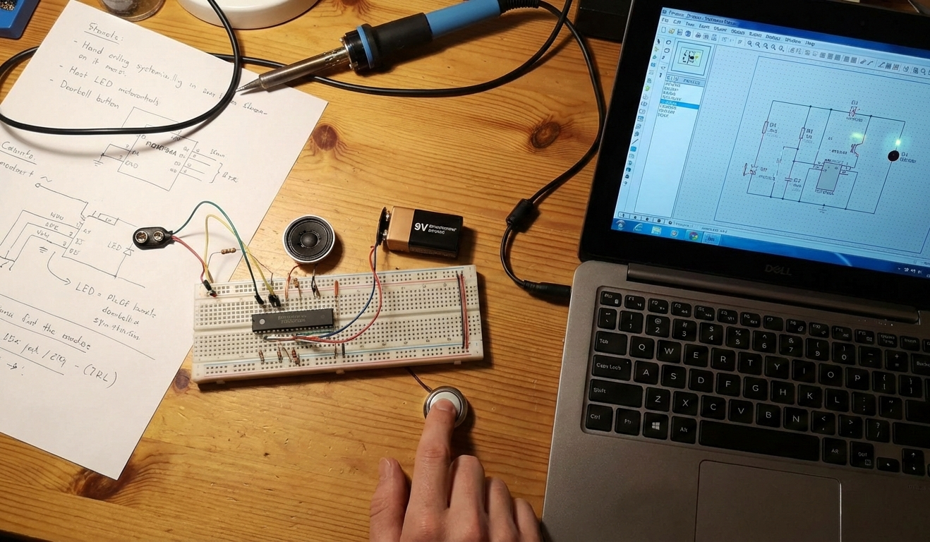
How the Project Works (Overview)
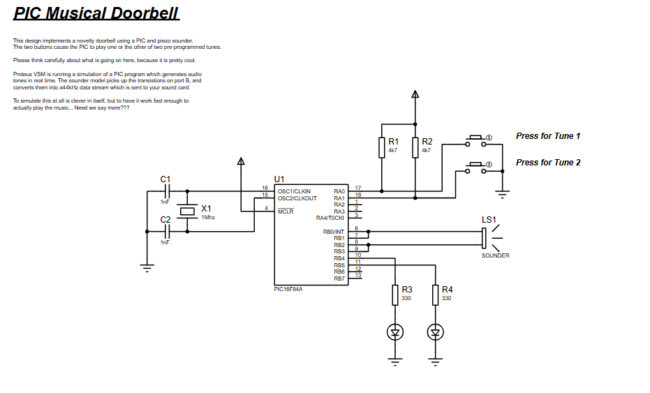
The PIC Musical Doorbell uses Timer0 interrupts to generate square-wave audio signals that drive a sounder.
When a button connected to PORTA is pressed, the microcontroller selects a corresponding tune stored in program memory.
Each tune consists of note and duration pairs, which are processed sequentially.
Pitch values are translated into timer reload values, producing accurate musical frequencies.
The result is a fully firmware-driven audio playback system without any external audio ICs.
Block Diagram / Workflow Explanation
Push Button Input (PORTA)
RA0 triggers Tune 1
RA1 triggers Tune 2
Tune Selection Logic
Firmware loads the starting address of the selected tune table
Tempo and timing parameters are initialized
Note Processing
Note code → pitch lookup table
Duration → delay loop counters
Timer0 & Interrupt Handling
Timer0 generates periodic interrupts
ISR toggles PORTB pins to create audio waveform
Sound Output
Square wave drives the sounder via PORTB
Key Features
Two selectable musical tunes via push buttons
Timer0-based tone generation without DAC
Interrupt-driven sound waveform toggling
Lookup tables for pitch and note duration
Fully software-controlled audio synthesis
Designed and tested using Proteus VSM
Components Used
PIC16F84A microcontroller
Piezo sounder / speaker
Push buttons (2×)
Resistors (pull-ups, current limiting)
External crystal oscillator (1 MHz)
Capacitors for oscillator stability
Applications
Musical doorbells
Embedded audio demos
Microcontroller music players
Educational projects for timers and interrupts
DIY sound generation systems
Explanation of the Code (High-Level)
The firmware begins by configuring PORTB as output and setting up Timer0 with a prescaler for tone generation.
The main loop continuously polls the push buttons on PORTA.
Once a button is detected, the corresponding tune pointer and tempo are loaded.
Each note is fetched from program memory using computed jumps via PCL and PCLATH.
Pitch values are converted using a lookup table, and Timer0 reload values control frequency.
An interrupt service routine toggles PORTB pins on every Timer0 overflow, producing the audible square wave.
The tune ends when a termination flag is detected, returning the system to idle state.
Source Code
Download LIST p=16F84 ; PIC16F844 is the target processor
#include "P16F84A.INC" ; Include header file
CBLOCK 0x10 ; Temporary storage
tempo
tptrl
tptrh
note
length
pitch
temp
dl1
dl2
ENDCComplete Source Code
Proteus Simulation
In Proteus VSM, the PIC16F84A runs in real time while Timer0 generates audio-rate interrupts.
Pressing either push button immediately starts playback of the selected tune.
The sounder output reflects accurate pitch and timing based on the firmware logic.
This simulation closely mirrors real hardware behavior, making it excellent for testing and learning.
(FAQs)
Conclusion
This PIC Musical Doorbell project is a compact yet powerful example of audio synthesis using a PIC microcontroller.
It demonstrates timers, interrupts, lookup tables, and structured firmware design in a clear, practical way.
Whether you’re learning embedded systems or building fun DIY electronics, this project delivers strong educational value with minimal hardware.
Complete File
PIC Musical Doorbell using PIC16F84A with Proteus Simulation
- Why is Timer0 used for sound generation?
Timer0 provides precise timing needed to generate musical frequencies using interrupts. - Can this project run on real hardware?
Yes, the design is hardware-ready and mirrors the Proteus simulation. - How are different notes generated?
Each note maps to a specific Timer0 reload value via the pitch lookup table. - Can I add more tunes?
Yes, additional tune tables can be added in program memory. - What happens when a REST note is detected?
The firmware disables tone output for the specified duration. - Can I change the tempo?
Tempo is controlled by a variable and can be adjusted per tune. - Why are interrupts required?
Interrupts ensure consistent waveform timing without blocking the main program. - Is an external DAC required?
No, square-wave audio is generated directly via GPIO toggling.
Related projects
PIC Stepper Motor Controller using PIC16F84A with Proteus Simulation
Introduction Stepper motors are widely used in embedded systems and DIY electronics projects where precise position control is required. This PIC Stepper...
Beginner Tutorials · PIC16C84Exploring the World of PIC Microcontrollers: An Architectural Overview
A Peripheral Interface Microcontroller (PIC), developed by General Instruments Microcontrollers in 1993, operates under software control and is programmed to execute various...
Clocks & Timers · PIC16F84AIN-8 single nixie tube clock using PIC16F84
After receiving one IN-8 tube from a friend (thanks), I decided to build myself a clock. This clock is more an ornament...
Programmers & ICSPCalculator Test using PIC24FJ64GA006 with Proteus Simulation
Introduction The Calculator Test using EASYHDL is a practical microcontroller project built on the PIC24FJ64GA006 and simulated in Proteus. This project demonstrates...
Programmers & ICSPPID Controlled Oven using TMS320F28027PT with Proteus Simulation
IntroductionThis project demonstrates a PID controlled oven implemented using a PICCOLO TMS320F28027PT microcontroller and verified through Proteus simulation.It is a practical microcontroller...
Programmers & ICSPPICCOLO Motor Controller Sample Design using TMS320F28023PT with Proteus Simulation
IntroductionThis project demonstrates a PICCOLO motor controller sample design implemented using the TMS320F28023PT Piccolo microcontroller and tested through Proteus simulation. It focuses...

Ibrar Ayyub
I am an experienced technical writer holding a Master's degree in computer science from BZU Multan, Pakistan University. With a background spanning various industries, particularly in home automation and engineering, I have honed my skills in crafting clear and concise content. Proficient in leveraging infographics and diagrams, I strive to simplify complex concepts for readers. My strength lies in thorough...