Summary of PIC16F1787 Programmer Board (for Almost all 40 pin 16Fxxx)
This project builds a PIC16F1787 development/programmer board on a ready-made PCB, with connections for programming (MCLR, Vdd, Vss, PDAT, PCLK), a 5V regulator, 40-pin socket, headers for peripheral access, optional LED and PC jack, and using PICKIT3 and MPLAB X for programming. The board can also program other 40-pin 16Fxxx devices with datasheet checks.
Parts used in the PIC16F1787 Development Board:
- PIC16F1787 microcontroller
- Ready made PCB board
- 5V regulator (LM7805)
- 40 pin jack
- Male connecting pins
- Female connecting pins/headers
- Push button
- 8.7k resistor
- Connecting wires
- LED (optional)
- Computer's jack (optional)
Intro
This is my first Instructable so I’m sorry for mistakes. Critics are always welcome 🙂
So in this project I made a development board for PIC16F1787. Now most of you guys aren’t familiar with this particular model. Some might even think why I chose 16Fxxxx series IC when I could have easily used 18Fxxxx series and had more fun.
Well for my project DC to 3 phase AC pure sinewave Inverter (I’ll try to make an instructable for that also), I found this IC very interesting indeed. You guys should check out its datasheet for its applications. It has built in 3 phase PWM generator and other cool stuff. Im attaching its datasheet.
Step 1: Items you will be needing
Items Needed:-
Must needed:-
- PIC16F1787 (ofcourse)
- Ready made PCB board
- 5v Regulator (LM7805 in my case)
- 40 pin jack
- Male and Female connecting pins
- Push Button
- 8.7k Resistor
- Connecting wires
Optional:-
- LED
- Computer’s Jack
Step 2: Circuit
The connections are all described in the picture attached. So feel free to observe it and ask where you don’t understand something.
MCLR, Vdd, Vss, PDAT, PCLK are needed to program the IC and they are connected to a male header/connecter so that Picket 3 can be used.
+5V DC are to be applied for PIC to work, remember NO MORE THAN 5 Volts. It will permanently damage the IC.
LED is optional as it is applied just to check whether
the PIC IC is working or not by using a toggling code.
Female headers are connected with the 40pin jack. These can be used in switching of many programs.
Step 3: Programming
Use Picket 3 for Programming. It is the best and trouble free programmer 🙂
I made a C++ based code for LED toggling. The compiler used my me is MPLAB X. It is user friendly and easy to make C programs.
My LED toggling Program is attached below.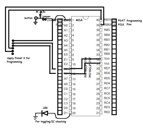
Step 4: Finished!!!
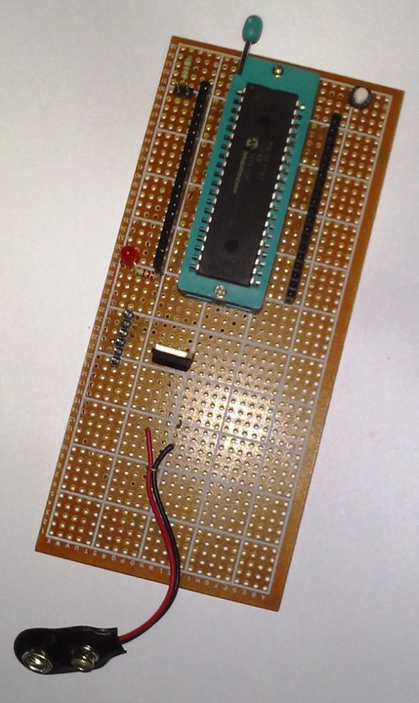
This is the final form after soldering the parts altogether. Hope you liked it. I will add more details in my future instructables. Stay tuned………..
Thankx for reading
P.S= 16F877 and 16F877A were also programmed by the same board. Consult datasheet before using this board for other 40 pin PIC controllers.
For more detail: PIC16F1787 Programmer Board (for Almost all 40 pin 16Fxxx)
- What microcontroller is used in this project?
PIC16F1787 is used in this project. - What voltage should be applied to power the PIC?
Apply +5V DC and do not exceed 5 volts. - Which programmer is recommended for programming the board?
PICKIT3 is recommended for programming the board. - Which pins are required for programming the IC?
MCLR, Vdd, Vss, PDAT, and PCLK are connected for programming. - What regulator is used to provide 5V?
An LM7805 5V regulator is used. - Is an LED required on the board?
The LED is optional and used to check the PIC with a toggling code. - Can this board program other 40-pin 16Fxxx PICs?
Yes, 16F877 and 16F877A were programmed with the same board, but consult datasheets before use. - What software and language were used for the example code?
MPLAB X was used and the example code is written in C/C++. - How are peripherals accessed from the board?
Female headers are connected to the 40-pin jack and provide access to peripheral pins.