Summary of AVR High Voltage Programming (Fuses Rescue)
This article details a DIY project to rescue unprogrammable AVR microcontrollers by resetting their fuses using high-voltage programming. The author, an electronics hobbyist, designed a simple PCB circuit to automate this process after encountering issues with cheap USBAsp clones. The device uses a "source" MCU and an LDO regulator to automatically burn default fuses onto a "destination" chip when the reset button is pressed.
Parts used in the AVR Fuses Rescue Project:
- "Source" Microcontroller (MCU)
- "Destination" Microcontroller (MCU) socket
- LDO Regulator (LM78L05 or compatible 5V LDO)
- LED indicator
- Reset button
- Breadboard (for initial prototyping)
- PCB board
- Vias
Half a year ago I restarted one of my old passions – electronics. I’ve studied electronics in college but that happened during the Middle Age (20yrs ago). While I was expecting this huge leap in schematics and what a hobbyist can do nowadays, I still had some difficulties in catching up.
One which frustrated me greatly was the fuses for AVR/PIC microcontrollers (MCUs). I found a lot of interesting schematics with MCUs and fuses is a very important aspect when programming them. However, because I was a newbie in this department, I didn’t want to spend too much on this so I bought quite cheap programmers from eBay. The PIC programmer worked fine but the USBAsp clone that I bought for AVRs was not a very good choice. An important percentage of my burning got screwed up because the fuses were wrongly programmed – most of the times the AVR became unrecognizable, it had a wrong ID, in other words it became almost dead/unusable.
Step 1: Concept and Schematic
I started looking on the web for a solution and I found a very good way to reset the fuses using high voltage programming (link here: http://denki.world3.net/avr_rescue.html). I suggest reading the link for a better understanding of how it works 🙂
It was fun building it on a breadboard for the first time but it became boring and time consuming starting with the second, third and so on.
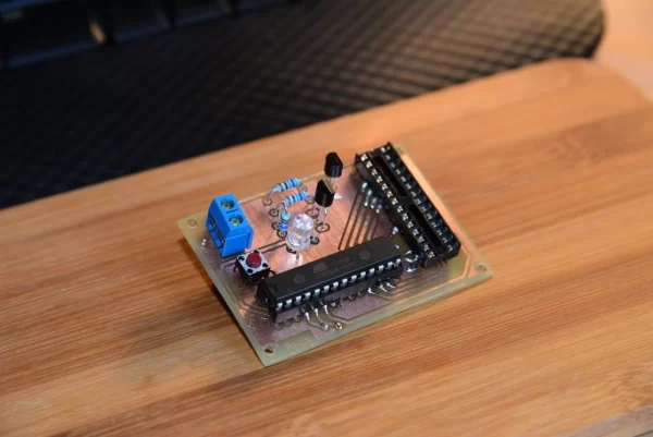
I decided to just put it on a PCB and have it handy whenever I need to quickly reset the fuses for an AVR. The schematic is very simple, I used minimum components, the lines between the “source” MCU and “destination” are not protected by 1K resistors and I also didn’t use an external crystal for the “source”. Powering the schematic and the “source” MCU is done via a simple LDO – LM78L05; I believe any 5V LDO given that it has the same pinout. I didn’t bother with filtering, it’s not quite important since the voltage noise is not (very) relevant for this circuit.
The AVR reset process is straight forward, after mounting the “destination” MCU in the IC2 socket, one has to power on the circuit. The LED will stay on until the Reset button is pressed; upon pressing the Reset button, the LED will go off and the default fuses will be burned on the “destination” MCU. When burning is complete, the LED will come on again. It will take few seconds to burn the default fuses, around 10 seconds, so don’t panic.
The EAGLE files and HEX for the “source” MCU can be found here:
– EAGLE CAD files – both schematic and board
– EAGLE CAD prints – both top and bottom layers
– HEX file for the “source” – yes, one has to program it first and then use this MCU as “source”
PS: I didn’t like the TO92 default pinout of the LDO so I’ve build a new library with the pins in line for ease of PCB design.One just has to copy it in the Eagle Lbr folder and load it in the software.
Attachments
- AVR_Fuses.brdDownload
- AVR_Fuses.schDownload
- AVR_Fuses_Top.pdfDownload
- AVR_Fuses_Bottom.pdfDownload
- AVR-Rescue-0.2.zipDownload
- LM78Lxx.lbrDownload
Step 2: Overview
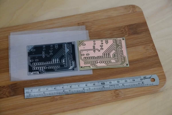
The schematic works well for me, it is doing what it’s supposed to do. The LED color is not important, it’s just something to let you know the circuit works. I tried to design the PCB with as less vias as possible and 5 vias seems reasonable. The end result may not look at its best, the surface soldering of the IC sockets could be a little difficult but it wasn’t a big deal and definitely not a show-stopper. I’m sure it can be improved using SMD components but I didn’t have any handy so I opted for through-hole. Anyone can customize the EAGLE files for their own use.
Cheers and have fun,
Source: AVR High Voltage Programming (Fuses Rescue)
- How can I reset fuses on an unrecognizable AVR microcontroller?
You can use a high voltage programming circuit that burns default fuses onto the destination MCU. - What components are required for the source MCU in this circuit?
The schematic uses minimum components and does not require an external crystal for the source MCU. - Which LDO regulator is recommended for powering the circuit?
An LM78L05 is used, though any 5V LDO with the same pinout will work. - Does the LED color matter in this design?
No, the LED color is not important; it simply indicates that the circuit is working. - How long does it take to burn the default fuses?
It takes around 10 seconds to burn the default fuses. - Can I customize the EAGLE files for my own use?
Yes, anyone can customize the EAGLE files for their own specific needs. - Why did the author switch from breadboard to PCB?
The breadboard method became boring and time-consuming after the first build. - Are 1K resistors used to protect lines between MCUs in this schematic?
No, the lines between the source and destination MCUs are not protected by 1K resistors.