Summary of Dual programmable keypad code lock using PIC18F452
This project is a dual programmable keypad code lock using a PIC18F452 that controls up to two relay outputs, supports optional LCD, low power sleep mode, and user-changeable 4-digit codes with auto-blocking after five wrong attempts. Kit, source (CCS C), PIC hex, PCB layout and Eagle schematics available.
Parts used in the Dual programmable keypad code lock:
- PIC18F452 microcontroller
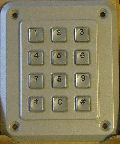
- Keypad(s) (professional, outdoor, or other compatible keypads) — up to two
- Relays (2 relay outputs)
- Power input supply (6 to 24 VDC range specified for outputs)
- Internal switching power regulator (on-board)
- Optional small LCD display
- Piëzo buzzer (high-pitched sound generator)
- Cables for keypad connection (supports up to 100 m)
- PCB (kit PCB provided)
- Miscellaneous passive components and connectors as per schematic (resistors, capacitors, headers)
Open electrical doors with your secret code only!
Here are the technical specifications:
- Up to two keypads may be connected to drive both relay outputs.
- Professional, outdoor or other keypads may be used.
- Relay outputs are configurable: output voltage +6 to +24VDC (from power input) or simple switch emulation.
- The small LCD is optional, and can be omitted.
- Low power operation with internal switching power regulator and microcontroller auto sleep mode: only 4 .. 8 mA at 12VDC
- The 4-digit secret codes can be changed by the user (previous code needed.)
- Auto blocking after 5 wrong attempts.
- High-pitched piëzo sounds when striking a key.
- Keypad cable length up to 100m.
-
- This product will be available as a KIT from our online shop.
- Source code (CCS C) can be purchased separately.
PIC hex file , pcb layout and schematics (Eagle) available.
structions for use:
-
Secret code input: type the 4-digit code and press the # key to activate relay output 1. Press the * key to activate relay output 2.
-
Changing the secret code: type the previous code and press # or * until the piëzo sounds (after 5 sec.) Then type your new 4-digit code and press # or * to finish.
Downloads: right-click & save as
For more detail: Dual programmable keypad code lock using PIC18F452
- How many keypads can be connected?
Up to two keypads may be connected to drive both relay outputs. - What type of keypads can be used?
Professional, outdoor or other keypads may be used. - How are the relay outputs configured?
Relay outputs are configurable as output voltage from +6 to +24VDC (from power input) or as simple switch emulation. - Is the small LCD required?
The small LCD is optional and can be omitted. - What is the power consumption?
Low power operation uses only 4 to 8 mA at 12VDC with internal switching regulator and microcontroller auto sleep mode. - Can the secret codes be changed by the user?
Yes, the 4-digit secret codes can be changed by the user; the previous code is needed to change it. - What happens after multiple wrong attempts?
The system auto blocks after 5 wrong attempts. - How do you activate relay outputs?
Type the 4-digit code and press # to activate relay output 1, or press * to activate relay output 2. - How do you change the secret code?
Type the previous code and press # or * until the piezo sounds (after 5 seconds), then type the new 4-digit code and press # or * to finish. - Are firmware and design files available?
PIC hex file, PCB layout and schematics (Eagle) are available; source code (CCS C) can be purchased separately.