Summary of Building your Dream Alarm Clock Using the PIC18
Summary: This lab guides students to build an alarm clock on a PIC18F4550 using C. It covers hardware setup (sensors, crystal, speaker, display, servo), MPLAB project creation, building and running provided source code, and required features: time display with blinking colon, periodic temperature display, button-based time/alarm setting, and alarm activation. Optional advanced features include selectable ringtones, servo bell ringing, and full-color LED effects.
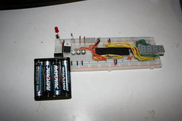
Parts used in the Building your Dream Alarm Clock Using the PIC18:
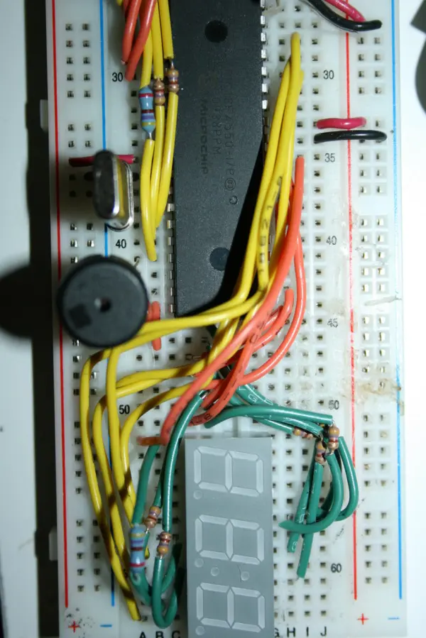
- PIC18F4550 microcontroller
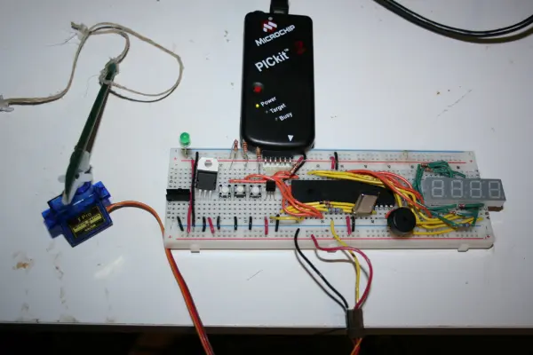
- Pickit2 programmer
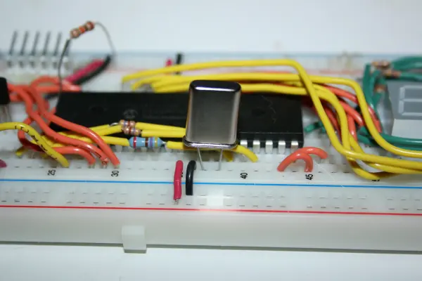
- 20 MHz crystal
- Speaker
- Seven-segment display (with decimal point and middle colon segment)
- 470-ohm resistor (for decimal point segment)
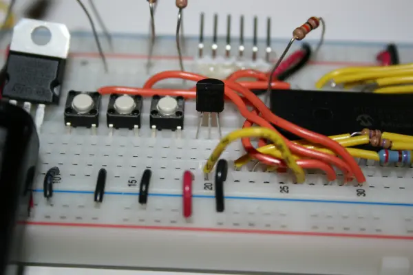
- Temperature sensor LM60
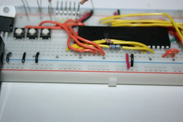
- Push buttons (three)
- Servo motor (optional)
- Wires/jumper cables
- Protoboard / breadboard
- Power supply (+5V and ground)
Objective:
In this laboratory session, your objective is to create an alarm clock using the C programming language. You will gain proficiency in writing “C” programs for the PIC18 microcontroller. Additionally, you will acquire knowledge on working with interrupts, employing digital-to-analog conversion, and implementing music playback on the PIC18.
This is a collaborative project, with each team limited to a maximum of two members. While individual work is an option, the grading criteria remain consistent for all project submissions.
Step 1: Initial Configuration
Commence by detaching the Full Color LED and securely storing it. You may opt to utilize it at a later stage in this project.
Move the button cables 2 positions to the right, that is they should be now in A28, A29, and A30
Begin by locating the temperature sensor, which can be identified as the black semi-cylinder with three legs and the label LM60. Be cautious not to mistake it for the other transistors. Place the temperature sensor into positions E19, E20, and E21 as indicated, ensuring that the flat side is oriented towards you. Connect A19 to +5V and A21 to 0V. Additionally, attach a wire leading to the center of the sensor, connecting it to A26, which serves as the analog input. It is crucial to verify the correct power connections for the temperature sensor to prevent any damage due to overloading.
“Install a 20MHz crystal on positions A37 and A38 to provide a more precise clock signal to the microcontroller. In previous projects, the CPU relied on the less accurate internal clock.”
Now connect the speaker to terminal A41 and ground. The speaker will play the tones using the PWM ouput from RC2.
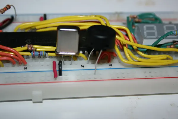
Next, you should attach a 470-ohm resistor with the color code Yellow-Violet-Brown to the segment associated with the decimal point. Connect this resistor between points B62 and B52. This resistor is identical to the ones used for the remaining segments. Additionally, establish a connection by running a cable from point A52 to I35.
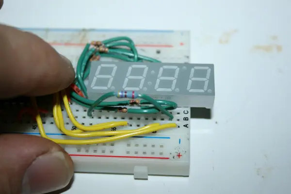
Connect a wire from A59 to I28 to establish the connection for the cathode of the middle “:” segment on the seven-segment display.
Step 2. Building your First C Program
Here are the instructions rephrased:
1. Begin by launching MPLAB IDE and establish a connection between Pickit2 and your breadboard.
2. Navigate to Project -> Project Wizard, and this will open the Project Wizard. Click on “Next.”
3. In “Step One: Select a Device,” ensure that PIC18F4550 is the chosen device and proceed by clicking “Next.”
4. In “Step Two: Select a language toolsuite,” pick the MPLAB C18 C Compiler, and click on “Next.”
5. In “Step Three: Create a New Project…,” click on “Browse” to specify the location for storing your lab6 files. Name the file “hello” in the “File Name” field, and then click “Next.”
6. In “Step Four: Add existing…,” click “Next.”
7. In the “Summary” section, press “Finish.”
8. Go to Project -> Build Options -> Project. Under the Directories Tab, select “Include Search Path” and click on “New.” Utilize the “…” button to browse for “C:\MCC18\h” and confirm by clicking “OK.”
9. Now, under “Library Search Path,” follow the same process by selecting “Show Directories for” and clicking “New.” Use the “…” button to navigate to “C:\MCC18\lib” and click “OK.”
10. To proceed, select File -> New and copy the provided file:
#include <p18cxxx.h>
#pragma config WDT=OFF // disable watchdog timer
#pragma config MCLRE = ON// MCLEAR Pin on
#pragma config DEBUG = ON// Enable Debug Mode
#pragma config LVP = OFF// Low-Voltage programming disabled (necessary for debugging)
#pragma config FOSC = INTOSC_EC // High Speed
void main()
{
// Make all bits of PORTD digital output
TRISD = 0x0;
PORTD = 0xFF;
// Make all bits of PORTB digital output
TRISB = 0x0;
PORTB = 0x0;
while (1) {
// Delay
unsigned int i = 0xFFFF;
while (i>0) i–;
// Turn on and off all segments of the seven segment display
PORTD = ~PORTD;
}
}
- Go to the “File” menu and choose “Save As,” then enter the filename “hello.c.”
- Within the Project Window, labeled as “hello.mcw,” perform a right-click inside the “Source Files” section and opt for “Add Files.” Subsequently, select the file “hello.c” and click the “Open” button.
- Now, initiate the project build by navigating to the “Project” menu and selecting “Build All.”
- To program the PIC18 microcontroller, go to the “Programmer” menu and choose “PicKit2.”
- Execute the program by selecting “Programmer” and then clicking on “Program,” followed by “Release From Reset.” You should observe all the segments of the display flashing.
Step 3. Running the Base Program
1. First, fetch the lab6-src.zip file and place it in your current working directory. Then, proceed to extract its contents.
2. Close MPLAB, reopen it, and navigate to Project->Open. Choose the lab6-src directory that you previously extracted and select the “clock” project.
3. Go to Project->Build All, and subsequently, choose Programmer->Program and Programmer->Release from Reset.
At this stage, you will hear a rendition of “Happy Birthday to You,” and the display will begin counting in seconds. To increment the counter’s first digit, simply press the first button.
You’ll be utilizing this program as the foundation for your alarm clock project. All the specific register variable names can be found in the C:\MCC18\h\p18f4550.h file.
Step 4. The Alarm Clock
You will create your alarm clock with the following essential features:
Essential Features (70% of the total grade)
These are the core functions expected in your clock, accounting for 70% of the overall grade.
1. The display must indicate the current hour and minutes, with a blinking “:” between them, updating every second.
2. Display the room temperature for 2 seconds every 10 seconds.
3. Utilize three buttons to modify the hour, minute, set the alarm time, and toggle the alarm on/off. It is advisable to employ one button to switch between different modes: displaying the time, setting the hour, setting the minutes, setting the alarm hour, setting the alarm minutes, and toggling the alarm on or off. The other two buttons can be used to increment and decrement the minutes and seconds. You may also enable digit-by-digit updates on the display and flash the currently edited digit.
4. Activate the alarm when the set alarm time is reached.
Advanced Features (30% of the total grade)
These are additional functionalities you can incorporate into your clock, accounting for 30% of the total grade. Some ideas include:
1. Choose and preview the alarm ringtone.
2. Use the servo in your kit to ring a bell a specific number of times corresponding to the hour (e.g., ring the bell 5 times at 5:00).
3. Employ a full-color LED to create ambient lighting and randomly change the color tone over time.
Your clock will also be evaluated based on its ease of use and intuitiveness.
Extra: Connecting the Servo
The servo is a combination of a motor and gear mechanism that enables angular movement to a specified number of degrees. The angle is determined by adjusting the pulse width sent to the servo. A 1500μs (microseconds) pulse will position the servo at 0 degrees, approximately 1000μs for -90 degrees, and roughly 2000μs for +90 degrees. These pulses are sent approximately every 20 milliseconds.
If you opt to use the servo, follow these steps for connection:
1. Cut three wires, each around 2 inches in length.
2. Connect the brown wire from the servo to the ground (0V) and the red wire to +5V.
3. The orange wire should be connected to RE0 or A32 on the protoboard.
The provided “lab6-src” program includes a procedure called “drive_servo(angle” that demonstrates how to control the servo. The servo will move from -90 to 90 degrees while playing the “Happy Birthday To You” song. The code generates pulses in a simple manner, which may not be highly precise but sufficient for moving the servo and, for instance, ringing a bell. For more precise movements, you can generate the pulses within a timer interrupt routine.
Source: Building your Dream Alarm Clock Using the PIC18
- How do I configure the PIC device and toolchain in MPLAB?
Select PIC18F4550 as device and MPLAB C18 C Compiler as the toolsuite in the Project Wizard, then create a new project and set include and library paths to C:MCC18h and C:MCC18lib respectively. - How do I add and build the initial hello.c program?
Create hello.c with the provided code, save it, add it to the project Source Files, then use Project -> Build All. - How is the temperature sensor LM60 connected?
Place LM60 with flat side facing you into E19-E21, connect A19 to +5V, A21 to 0V, and wire the sensor center pin to A26 as the analog input. - Where do I connect the 20 MHz crystal?
Install the 20MHz crystal on positions A37 and A38 for a precise clock signal. - How is the speaker connected and driven?
Connect the speaker between terminal A41 and ground; it is driven by the PWM output on RC2. - How do I wire the decimal point segment resistor?
Connect a 470-ohm resistor between B62 and B52 for the decimal point and run a cable from A52 to I35. - How is the middle colon cathode connected?
Connect a wire from A59 to I28 for the cathode of the middle colon segment. - How do I run the provided lab6-src base program?
Extract lab6-src.zip, open the clock project in MPLAB, Build All, then use Programmer -> Program and Release from Reset; the program plays Happy Birthday and counts seconds. - How should the three buttons be used for clock functions?
Use one button to switch modes (time display, set hour, set minutes, set alarm hour, set alarm minutes, toggle alarm) and the other two to increment and decrement values or edit digits as desired. - How do I connect the servo if used?
Connect servo brown to ground, red to +5V, and orange control wire to RE0 (A32); example drive_servo(angle) is provided in lab6-src.