Summary of PIC16F877A timer0 code + Proteus simulation
This tutorial explains using Timer0 and its interrupts on a PIC16F877A (20 MHz crystal) with C (HI-TECH) in MPLAB and Proteus simulation. Timer0 is configured with a 1:2 prescaler so the 8-bit timer overflows every ~102 µs at 5 MIPS; each overflow triggers an interrupt that toggles RB0. InitTimer0 sets OPTION_REG, enables T0IE and GIE; the ISR toggles RB0 and clears the T0IF flag. Example code and Proteus schematic are provided for modification and download.
Parts used in the PIC16F877A Timer0 Example:
- PIC16F877A microcontroller
- 20 MHz crystal oscillator
- Proteus simulator (for verification)
- MPLAB IDE
- HI-TECH C compiler
- LED (connected to RB0)
- Resistor for LED current limiting
This PIC16F877A microcontroller tutorial answers the question,
” How to use timer0 of PIC16F877A and how to handle its interrupts? ”
Using PIC16 simulator (Proteus) you can verify this PIC timer0 code and change it according to your needs. This code is written in C language using MPLAB with HI-TECH C compiler. You can download this code from the ‘Downloads‘ section at the bottom of this page.
It is assumed that you know how to blink an LED with PIC16F877A microcontroller. If you don’t then please read this page first, before proceeding with this article.
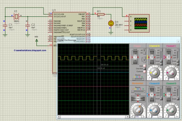
The following diagram (made in Proteus) shows the PIC microcontroller circuit diagram.
In this circuit, PIC16F877A is running on external crystal of 20MHz value. RB0 pin is toggled every time timer0 expires and executes it’s ISR[1] code. In the above figure, it is clear that after approximately every 100usec, RB0 pin is toggled i-e timer0 expires. You can easily change this value in the code.
Code
The main function code is shown below.
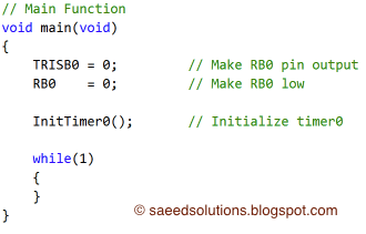 |
| Main function for timer0 of PIC16F877A |
In the main function, firstly TRISB0 is made zero to make RB0 pin an output pin, also RB0 pin is made zero. After that, InitTimer0() function is called which initializes timer0. Rest of the work is done in timer0 interrupt service routine. Every time timer0 expires RB0 pin is toggled.
The code used to initialize timer0 is shown below.
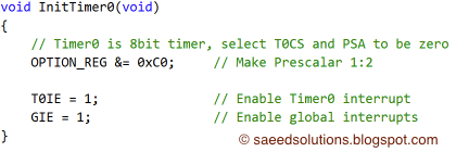 |
| InitTimer0 function code for PIC16F877A |
 Timer0 interrupt service routine code is shown below.
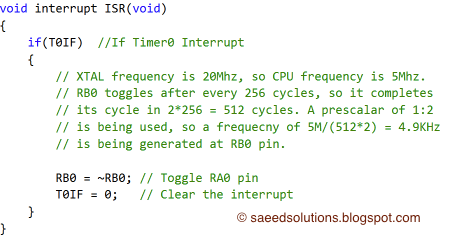 |
| Timer0 interrupt service routine |
This is just an example code for timer0 of PIC16F877A microcontroller. You can modify it to fulfill your circuit requirements.
For more detail: PIC16F877A timer0 code + Proteus simulation
- How is Timer0 configured in this example?
Timer0 is initialized with OPTION_REG to use a 1:2 prescaler, configured as an 8-bit timer that increments every two clock cycles. - What clock and instruction speed is used?
The PIC runs on a 20 MHz crystal and operates at 5 MIPS as stated in the article. - How often does Timer0 overflow and trigger an interrupt?
With a 1:2 prescaler at 5 MIPS the 8-bit timer overflows approximately every 102 microseconds. - What happens in the Timer0 interrupt service routine?
The ISR toggles RB0 and clears the Timer0 interrupt flag (T0IF). - How is RB0 configured in the main function?
TRISB0 is set to output (zero) and RB0 is initialized low before calling InitTimer0. - Which bits enable Timer0 interrupt and global interrupts?
T0IE enables the Timer0 interrupt and GIE enables global interrupts. - Can the overflow interval be changed?
Yes, the article states you can change the value in the code to adjust the overflow timing. - What tools are recommended to verify the code?
Proteus simulator is recommended to verify the PIC Timer0 code and test changes.