Summary of Precision Temperature Monitoring in Boiling Water with PIC Microcontroller
Summary (under 100 words): This paper describes a boiled-water temperature measurement and cooling system using a PIC18F452 microcontroller and LM35 sensors. Heated water from Boiler I is monitored; when it exceeds a setpoint the solenoid opens and hot water flows through GI pipes to Boiler II. If temperature remains high, Boiler III’s sump motor sprays cool water through timed control valves to lower temperature to the programmed set value, then stores cooled water for reuse. Hardware includes LCD, ULN2003-relay driver, MAX232 serial interface, PCBs designed in EAGLE, and firmware in Embedded C using MPLAB.
Parts used in the Boiled Water Temperature Measurement System:
- Boiler I (14.5 in height, 11.5 in diameter)
- Boiler II (15 cm height, 6 in diameter)
- Boiler III (10 cm height, 5 in diameter)
- Test tubes (10 in length, 1 cm diameter)
- Connecting tube I (1 meter)
- Connecting tube II (1/2 meter)
- GI metal pipe I (2 feet, 1.5 in diameter)
- GI metal pipe II (2 feet, 1 in diameter)
- Plastic tube (3 meters)
- Control Valve I
- Control Valve II
- Control Valve III
- Control Valve IV
- Water heater (230 V, 50 Hz, 5 A)
- Solenoid valve (230 V, 50 Hz, 5 A)
- Sump motor (230 V, 50 Hz, 5 A)
- Temperature Sensor I (LM35)
- Temperature Sensor II (LM35)
- PIC microcontroller 18F452
- PIC microcontroller manual kit
- ULN2003 relay driver IC
- Relays (12 V)
- LCD display
- MAX232 serial communication driver IC
- Serial port connector
- PCB designed using EAGLE
ABSTRACT
In the industrial setting, accurately measuring the temperature of boiled water is a crucial undertaking. This paper presents the design and implementation of a temperature measurement system for boiled water utilizing a PIC microcontroller, specifically the PIC 18F452, and a temperature sensor from National Semiconductors, the LM35. The designed system is employed to gauge the temperature of the boiled water within a designated tank. Upon reaching a predetermined temperature, the high-temperature relay board activates, initiating control over the solenoid valve. To mitigate the elevated temperature of the boiled water coursing through the metallic pipe, a cooling mechanism is employed by releasing cool water through controlled valves. Manual control of these valves is adjusted based on the temperature requirements. Consequently, the outcome is achieved by diminishing the high temperature. The resultant low-temperature water is then accumulated in Tank III. Subsequently, following a comparison between the reduced temperature and the programmed temperature set value, the cooled water is prepared for distribution to various industrial purposes.
I.INTRODUCTION
The power plant section is a crucial department within the industry, featuring multiple boiling sections that generate high-temperature water with steam-level temperatures. This steam is utilized for power generation, powering the turbine section. Once power is produced, the steam waters are distributed to various plants for reuse. If the high-temperature supply is reduced to a lower temperature, it becomes suitable for other plants requiring lower temperatures.
This paper outlines the current study involving the separation of water into different temperature ranges based on specific needs. Water is an essential requirement in all industries, being utilized at various stages. In some cases, water is obtained along with the final product at high temperatures, rendering it unusable. Discharging such high-temperature water directly into the soil is not viable as it sterilizes the soil. Therefore, the water must be normalized before discharge, making it suitable for reuse when it attains standard physical and chemical properties. The Boiled Water Temperature Measurement System is employed to measure water temperatures at different points and collect water at various temperatures, enabling its versatile use for different purposes.
II.EXPERIMENTAL DESCRIPTION
Materials: Boiler I (dimensions: 14.5 inches in height, 11.5 inches in diameter), Boiler II (height: 15 cm, diameter: 6 inches), Boiler III (height: 10 cm, diameter: 5 inches), Test tubes (length: 10 inches, diameter: 1 cm), Connecting tube I (length: 1 meter), Connecting tube II (length: 1/2 meter), GI metal pipe I (length: 2 feet, diameter: 1.5 inches), GI metal pipe II (length: 2 feet, diameter: 1 inch), Plastic tube (length: 3 meters), Control Valve I, II, III, IV (height: 1.15 feet, diameter: 1 cm), Water heater (230 volts, 50 Hz, 5 A), Solenoid valve (230 volts, 50 Hz, 5 A), Sump motor (230 volts, 50 Hz, 5 A), Temperature Sensors I, II (LM35), PIC microcontroller 18F452, and PIC microcontroller manual kit.
Mechanical Setup: Mechanical Configuration: The exit of Boiler I is linked to the entry point of GI metal pipe I via a Solenoid valve, illustrated in the figure. Boiler I is equipped with a water heater device and a temperature sensor instrument. GI pipe II is interlinked with GI pipe I using four control valves of equal length, as depicted below. On one end of the control valve connected to GI pipe II, there is a adjustable nozzle-like arrangement. Boiler II is positioned at the exit of GI pipe I and incorporates a temperature sensor instrument. Boiler III is fitted with a motor connected to one end of GI pipe II through a plastic tube.
The opposite end of GI pipe II is connected to a plastic tube in a manner that allows the end of the plastic tube to enter Boiler III.
Design of Block Diagram: This system comprises three boilers, denoted as B1, B2, and B3. The initial boiler, B1, is equipped with a water heater element and a temperature sensor. In contrast, the second boiler, B2, features a temperature sensor. The third boiler, B3, incorporates a sump motor designed for spraying cool water during the processing phase.
Upon activating the PIC Microcontroller hardware circuit, the first boiler’s water is heated, with the temperature monitored by a temperature sensor. When the water temperature reaches a predetermined level, such as 90ºC, the solenoid valve is triggered to open.
Subsequently, the heated water from the first boiler is transferred to the second boiler through a sequence involving a connecting tube (CT 1), a metal pipe (GI 1), and another connecting tube (CT 2). In the second boiler, the temperature of the received hot water from the first boiler is once again gauged.
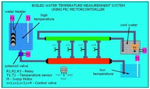
Our objective is to lower elevated temperatures and maintain a consistent temperature according to our desired setting. The fixed constant temperature is programmed, and to sustain it, the third boiler employs an automatic water spray system through small nozzles as specified in the program. For instance, if we set the constant temperature to 50ºC and the initial boiler outlet temperature is 90ºC (high temperature).
Upon reaching the second boiler, the sump motor of the third boiler activates as soon as the sump motor switch is turned on. The third boiler, containing cool water, circulates through the metal pipe GI 2, and the outlet at GI 2 is again connected to the third boiler to prevent it from drying out. Drying out the third boiler can result in a fault with the sump motor.
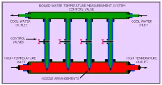
Operation of Control Valves: Metal pipe GI 2 is equipped with four control valves, namely CV1, CV2, CV3, and CV4, and is connected to metal pipe GI1. Each control valve has a time gradient. The spray of cool water process is halted if the temperature of the second boiler drops below 50ºC. On the contrary, if the temperature exceeds the constant threshold of 50ºC, the spray of cool water process persists. Consequently, the sump motor in the third boiler, responsible for the neat cycle, will be toggled ON and OFF in accordance with this temperature condition. This cycle repeats continuously.
HARDWARE DESCRIPTION
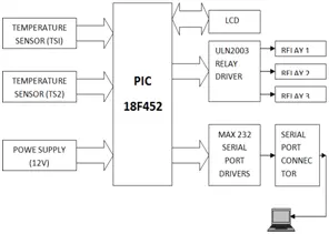
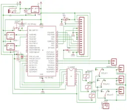
A. Hardware Configuration: For this investigation, a PIC microcontroller 18F452 is employed, operating at a voltage of 5V and a frequency of 8MHz. The microcontroller features five ports: A, B, C, D, and E. Port A functions as an analog channel and is linked to the temperature sensors. Port C is interfaced with the ULN 2003 relay driver IC, which operates at 12V and is subsequently connected to the relay. Port B is associated with the LCD display. The Rx and TX port pins of the PIC microcontroller are linked to a serial communication driver IC, Max 232, which is further connected to a serial port connector. This serial port connector can be attached to a computer.
Objective of the Project:
The primary goal of this project is to gauge the temperature of boiled water in analog format. A circuit equipped with the IC-LM 35 temperature sensor is employed to assess the temperature of the boiled water. The temperature data acquired is then transmitted via the PIC microcontroller. The microcontroller reads and processes the incoming data.
Subsequently, the output from the PIC microcontroller is directed to the LCD display.
The project involves two main tasks: (i) interfacing the temperature sensor and LCD with the microcontroller and (ii) transferring the parameter values through the microcontroller.
IV. TEMPERATURE MEASUREMENT DESCRIPTIONS
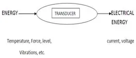
A. Temperature Principle: Temperature refers to the extent of heat or cold in a body. The internal resistance of a material changes in accordance with variations in temperature.
B. Detection Apparatus: Termed as a transducer, a sensor transforms signals into voltage, current, resistance, or capacitance. The block diagram provides a summary of the preceding explanation.
In this undertaking, the focus lies on temperature measurement—an essential aspect in various industries. Different methods of temperature measurement are employed in industries, each tailored to specific temperature ranges.
For instance, the LM35 serves the purpose of measuring temperatures within the range of -55˚C to +150˚C. The LM35 series comprises precision integrated-circuit temperature sensors, featuring an output voltage that is linearly proportional to the Celsius temperature. This gives the LM35 an edge over linear temperature sensors calibrated in ° Kelvin, eliminating the need for users to subtract a substantial constant voltage from its output for convenient Centigrade scaling. When dealing with temperatures exceeding 1000˚C, Thermocouples become the preferred choice for accurate measurement.
IV. PCB LAYOUT AND DESCRIPTION
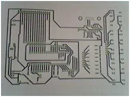
A. Designing PCBs for PIC Microcontrollers: Utilizing EAGLE editions, the PCB incorporates an optional auto router module or schematic editor in the Layout Editor. This tool enables the creation of Printed Circuit Boards.
The PCB includes features such as a serial port interface with an LCD display, interfacing with LM35 temperature sensors and relays, and supporting various interfaces.
IV. SOFTWARE DESCRIPTION
A. MPLAB: The code is crafted in Embedded C within the MPLAB IDE.
The MPLAB Integrated Development Environment (IDE) serves as a comprehensive toolset designed for the creation of embedded applications utilizing Microchip’s PIC and PIC microcontroller. MPLAB stands out as a robust and feature-rich development tool tailored for PIC microcontrollers. Its aim is to offer programmers the simplest solution for developing applications in the field of embedded systems.
The PIC microcontroller stands as the most widely used 8-bit chip globally, chosen for its efficiency across a diverse range of applications. It naturally becomes the preferred option for building embedded systems when considering a set of hardware components for various boards.
- What microcontroller is used in the system?
The PIC18F452 microcontroller is used in the system. - How is temperature sensed in the boilers?
Temperature is measured using LM35 temperature sensors connected to the PIC microcontroller. - Can the system lower water temperature automatically?
Yes, the system uses Boiler III sump motor and timed control valves to spray cool water and reduce temperature automatically according to the programmed setpoint. - What triggers the solenoid valve to open?
The solenoid valve is activated when Boiler I water reaches a predetermined temperature setpoint, for example 90ºC. - How is temperature information displayed?
The PIC microcontroller sends measured temperature data to an LCD display. - What software and language are used to develop the firmware?
Firmware is developed in Embedded C using the MPLAB IDE. - How does the system prevent Boiler III from drying out?
The outlet of GI2 is connected back to Boiler III to prevent drying and avoid sump motor faults. - What is the role of the ULN2003 in the hardware?
Port C of the PIC interfaces with the ULN2003 relay driver IC, which drives the relays used in the system. - How are serial communications handled?
The PIC Rx and Tx pins connect to a MAX232 serial driver and a serial port connector for computer connection.