Summary of Exploring the PIC16F88 Microcontroller for Remote-Controlled Robotics
Design summary (under 100 words): A PIC16F88-based spherical robot platform inside an acrylic shell, driven by two geared DC motors on a 3D-printed chassis. It uses a FlySky 2.4 GHz RC link, ADC-read receiver channels (via RC low-pass filters), PWM motor control through an L293D H-bridge, a battery level indicator on a seven-segment display (via SN7447AN), and a tilt sensor with buzzer alarm. Modular subsystems were breadboarded, combined, and coded; lessons emphasized time management, simpler testing interfaces, and hardware noise mitigation.
Parts used in the Spherebot:
- Microchip PIC16F88-I/P microcontroller
- Texas Instruments SN7447AN BCD to seven-segment decoder
- L293DNE quadruple half H-bridge driver
- LM7809C linear voltage regulator
- LM7805CT linear voltage regulator
- FlySky FS-I6-M2 transmitter
- FlySky FS2A 2.4 GHz four-channel receiver
- Two geared DC motors
- Seven-segment display
- Single-tone buzzer
- Tilt switch sensor
- LiPo battery
- Resistors, capacitors, diodes (for filtering, decoupling, and H-bridge protection)
- 3D-printed chassis
- Acrylic sphere shell
I. Design Summary
The objective of this mechatronics system design project is to develop a straightforward control and interface platform for robotics using a Microchip PIC processor. The aim is to create a versatile platform capable of accommodating various sensors, displays, and outputs, and it should be mobile while being controlled through 2.4GHz remote signals.
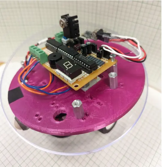
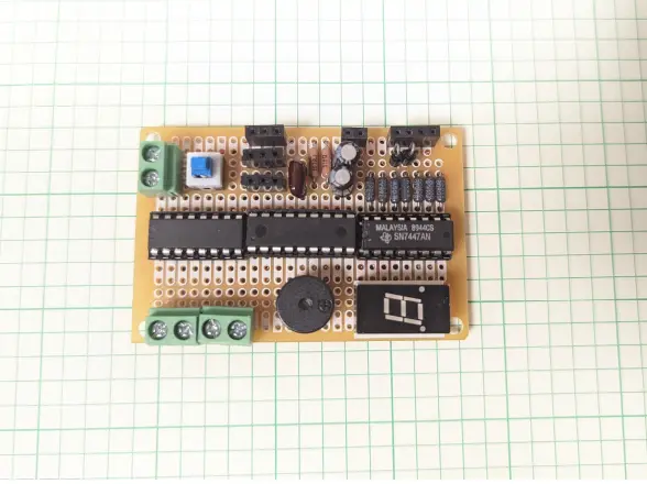
To add a unique twist to remote-controlled robotics, we’ve designed this robot to be enclosed within an acrylic sphere. It’s supported by a 3D-printed chassis that houses two geared DC motors at the bottom of the sphere. In the middle of the sphere, there’s a flat, circular platform that holds the control board, sensors, and outputs. You can see this setup in the project’s final photograph. The spherical design of the robot offers several advantages in terms of mobility and maneuverability compared to the common four-wheeled chassis. It can navigate through wet, sandy, or rough terrain without the risk of getting wheels or axles stuck, and it can orient itself in any direction by rotating around a single point. The shell also provides protection for the robot’s electronics and sensor payload in challenging environments, preventing submersion in liquids or damage from external forces.
For this project, we incorporated a battery level indicator and a tilt sensor to notify the user of instability or control issues. A common problem with less expensive remote-controlled vehicles is an abrupt loss of power due to a depleted battery. The battery sensor addresses this issue by displaying a numeric reading from zero to five to indicate the remaining charge. Additionally, an orientation warning system emits a loud beep when the robot is no longer oriented correctly, which can affect its steering. This sensor can also be configured by the robot’s processor to correct its motion. Furthermore, the robot’s design allows for easy customization once the foundational platform is completed.
II. System Details
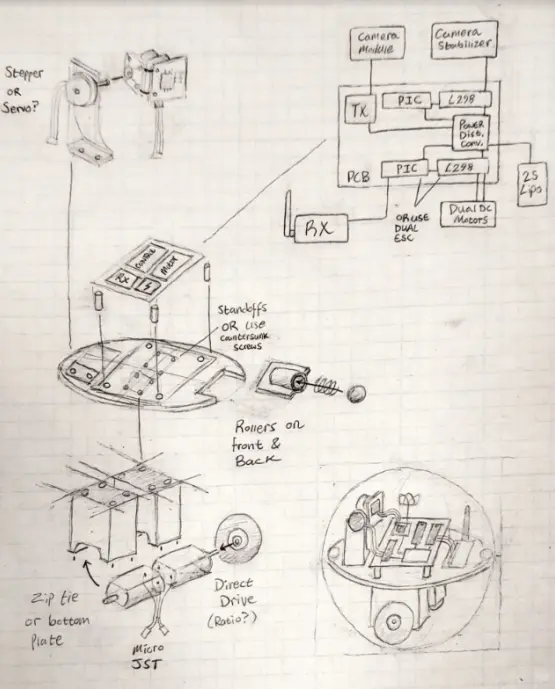
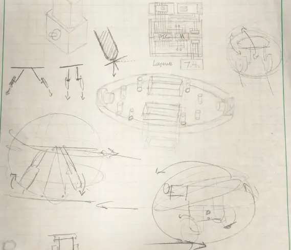
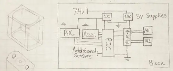
The initial idea for this device was to have the flexibility to accommodate multiple small sensors enclosed within a transparent acrylic shell. Originally, our concept revolved around incorporating a camera with a stabilization motor as the primary sensor for our project. However, to ensure that we could complete the project within our timeline, we made the decision to remove the camera and instead integrate a battery sensor and a tilt sensor. Below, you’ll find sketches generated during the early stages of our design process, outlining the fundamental circuitry requirements for this device. We also brainstormed various physical arrangements for the board, sensors, and motors to facilitate the design of the chassis in Fusion 360, aiding in the prototyping phase.
After finalizing the initial design sketches and determining how the PIC would interface with its inputs and outputs, the next step involved individually wiring and testing each subsystem on breadboards. This was done with basic programs running on the PIC.
Certain aspects of the design proved relatively straightforward to interface. For example, the warning buzzer and seven-segment display operated on a 5V supply and could be controlled using simple digital pulses, simplifying the wiring process. In the case of the display, we employed an SN7447AN BCD-to-seven-segment decoder chip to reduce the number of digital output pins needed for its operation. This meant that by transmitting a four-bit number from four pins on the PIC, we could illuminate the seven segments in any desired configuration.
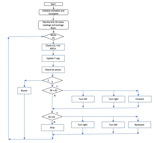
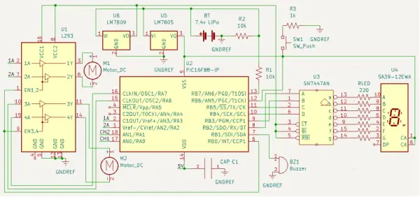
Managing the motors followed a similar pattern. The PIC received signals for left, right, up, and down movements from the receiver on its analog-to-digital converter pins. These signals were converted into DC signals using passive lowpass RC filters. Subsequently, the PIC calculated signal averages to mitigate noise introduced by the filters. The PIC then generated high or low signals for the motor ports and used a separate port for PWM (pulse width modulation) to control the motor speed. With this setup, the motors were capable of propelling the robot in the four cardinal directions and the four corners. The resulting logic and functionality can be observed in the accompanying figure.
The complexity increased significantly as we started to combine all these components and devise a coding system for controlling the device with our RC transmitter and receiver duo.
III. Design Evaluation
The final prototype was functional in modular components of the entire system. The individual sensors exhibited repeatable functionality, with a minimal variance in the number of trials that resulted in failure compared to successful outcomes. To display the battery level on our output screen, we employed a seven-segment display. The output from the PIC consisted of a four-bit number ranging from zero to five. To convert these signals from the PIC into a format suitable for the seven-segment display, we utilized a BCD to seven-segment display converter. Since the battery operated above the 5V maximum of a PIC port, the PIC received voltage from the center node of a voltage divider, and this aspect worked successfully. It’s worth noting that the utilization of the BCD to seven-segment converter and the seven-segment voltage polarity was not covered in the textbook and required some external research but not to a significant extent. For these reasons, we believe this section of the project deserves a score of 15.
For audio output, we employed a single-tone buzzer, which met the audio output requirement effectively. However, this category required the least additional research. This element was crucial for debugging the tilt sensor, as it could be represented using an LED and a resistor to indicate when the robot was tilted too far. It also helped us determine if the PIC reset, as the light flickered each time it rebooted. This element successfully made a sound when the battery level reached zero and the internal structure tilted excessively. We believe our innovative use of the sound sensor as a debugging tool deserves a score of 15.
Manual user input, implemented through a wireless remote controller, demanded extensive external research. The class and textbook did not provide adequate information to execute this without external research. The signal sent to the receiver was a point of significant investigation, initially appearing as PPM (Pulse Position Modulation) rather than PWM (Pulse Width Modulation). Subsequent testing and research confirmed that the signal was indeed PWM but with duty cycles ranging between about 5% and 9.5%. This complexity affected how the PIC received the signal, as the PIC16F88 had only one PWM port. To resolve this, we transformed the signal inputs into analog with low-pass filters and used the ADC functionality of two ports to process the signals. Given the extensive research and complexity, we believe the manual user input section deserves the maximum 20 points.
The automatic sensor category, which featured a tilt switch, required relatively less external research. Although there were initial circuitry challenges, we were able to make the tilt switch successfully transmit a high voltage when in an upright position and a low voltage when at an angle without significant complications.
The actuators, mechanisms, and hardware fulfillment encompassed multiple components and posed the most substantial challenges to our design. This category included motors with corresponding circuitry, the ball itself, the internal structure, and the wheels, all of which needed to function harmoniously. Troubles emerged when configuring the H-bridge with the PIC and the motors, resulting in PIC resets and erratic motor behavior. We overcame this problem with external research, introducing well-placed diodes and capacitors. Additionally, achieving the desired wheel and structure design, including determining the center of gravity, demanded extensive testing and experimentation. Given the complexity of this category and the substantial research and trials, we believe it deserves more than 15 points, although not necessarily the full 20.
Lastly, the logic, processing, and control category also required extensive external research.
IV. Partial Parts List
The heart of this project relies on Microchip’s budget-friendly PIC16F88-I/P, which is readily obtainable for $4.90 through Digikey. This 18-pin microcontroller offers just the right number of digital I/O pins, ADC converters, and CCP modules to perfectly align with our project’s requirements.
To convert the four-bit output from the PIC into inputs suitable for the LCD display, we utilized the Texas Instruments SN7447AN BCD to seven-segment display converter. These components are available in a 16-pin DIP package, obtainable for $3.34 from Digi-Key.
Our DC motors were effectively driven by the L293DNE quadruple half H-bridge chip, packaged in a 16-pin DIP format. This component can be sourced from Mouser at a cost of $4.29. It offered a straightforward yet efficient solution for controlling bidirectional motion in our two DC motors using logic output.
The task of regulating power from our LiPo battery to the rest of the circuit was entrusted to the LM7809C and the LM7805CT linear voltage regulators. These regulators, capable of delivering up to 1A of power, were responsible for powering the motors and all other components, respectively. Each of these components is available for $3.41 from Mouser.
For remote control, we utilized the FlySky FS-I6-M2 transmitter. Although it cost $65 when new, we chose this controller for testing purposes due to its existing availability and a comprehensive range of settings, tuning options, and control functionalities that greatly facilitated our experimentation and troubleshooting. It’s worth noting that a more cost-effective and simpler alternative could have been considered, given the functionality embedded in our final design.
Finally, the FlySky FS2A receiver was employed, operating at 2.4 GHz and offering four channels. It could be configured to produce a form of PWM, which was pivotal in our development and testing phases. These compact receivers are available domestically for $16.89 on Amazon, and can often be acquired at lower costs from international sources on platforms like eBay.
V. Lessons Learned
Like most project groups, our most significant lesson learned revolved around time management. Despite commencing work on our circuit, code, and hardware earlier than many other groups, we still found ourselves under considerable time constraints. It became evident that once project ideas are taking shape, it’s essential to initiate the construction phase promptly. Although this can be challenging, especially with concurrent coursework, it could have alleviated a significant portion of our end-project stress.
Moreover, we discovered that problems can emerge at every stage of the process, even within seemingly straightforward subsystems. A prime illustration for us was encountered with the seven-segment display. What initially seemed like a complex issue involving the PIC or power management system, leading to hours of frustration, boiled down to a simple mix-up related to the display’s part number and whether it was common-anode or common-cathode. It’s often the smallest, seemingly insignificant factors that can cause the most significant headaches.
Expanding on the concept of troubleshooting and debugging, we recognized the value of enhanced user interfacing within our project. While the user interface was primarily focused on device control through the transmitter, it wasn’t an effective method for testing outputs since we couldn’t be certain if the code interpreting the transmitter signal worked flawlessly. Incorporating a 4-way DIP switch into our design could have facilitated rapid and easy testing of uploaded programs and potentially accommodated additional functionality down the line.
Another valuable lesson was to simplify needlessly complex elements. We encountered a challenge where the input signal from our receiver was PWM, and we also required one of our outputs to be in PWM. This posed an issue as the PIC we used had only one CCP module, and we faced difficulties getting the pulsein function to work. We invested a substantial amount of time attempting to find a workaround in the code without success. Ultimately, we realized that a simple RC circuit could yield an average output voltage from the receiver, which we could then process using an internal ADC. This approach proved effective and saved us a significant amount of trouble.
Creating new code files whenever trying something new would have spared us countless hours of work. One particular instance was during our work on the PWM output for motor control. We experimented with various techniques and occasionally reused the same file for different approaches. However, we ultimately adopted aspects of an earlier solution but had overwritten the code. While this specific incident didn’t set us back considerably, frequent errors of this nature can accumulate and become a substantial time sink.
Lastly, we realized the importance of not overreaching in our project design. We had chosen an ambitious project from the outset, although we did simplify it by eliminating the camera module and its stabilization system. However, the overall design remained quite ambitious, especially given the time constraints. Nevertheless, opting for a project of this complexity allowed us to learn more than we would have otherwise, making it exceptionally rewarding to witness the final product in action.
VI. Appendix
Final Demonstration Code
‘Name : finalcode.BAS
‘Authors : Clyde J.
‘ : Matthew R.
‘ : Max U.
‘Date : 5/16/2022
‘Version : 2.0
‘Notes : Remote-Controllable Robotics Platform
‘ : Final Project Demo Code
‘ Configuration for PIC setup without external oscillator
‘ or MCLR pin reset function enabled
#config
__CONFIG _CONFIG1, _INTRC_IO & _PWRTE_ON & _MCLRE_OFF & _LVP_OFF
#endconfig
‘ Set up ADC functionality for proper size and clock speed
DEFINE ADC_BITS 10 ‘ Set number of bits in result
DEFINE ADC_CLOCK 3 ‘ Set clock source (3=rc)
DEFINE ADC_SAMPLEUS 15 ‘ Set sampling time in uS
‘ Set up internal oscillator at 8MHz
define osc 8
OSCCON.4 = 1 : OSCCON.5 = 1 : OSCCON.6 = 1
‘ Define variables for 7-segment binary input
sevend var PORTB.4
sevenc var PORTB.5
sevenb var PORTB.2
sevena var PORTB.3
speaker var PORTB.1 ‘ Speaker output variable
tilt var PORTB.6 ‘ Tilt switch input variable
‘ PWM and motor direction output variables
pwmsig var PORTB.0
fowardleft var PORTA.2
backwardleft Var PORTA.3
fowardright var PORTA.7
backwardright var PORTA.6
‘ Configure port tristate buffers for inputs/outputs
TRISA = %00000011
TRISB = %11000000
‘ Configure ANSEL register to use ADC at AN0, AN1, AN7
ANSEL = %1000011
‘ Configure CCP module and time period register for PWM out
CCP1CON = %00001100
T2CON = %00000110
PR2 = 124
‘ Program variables
battlevel var word ‘ Adjusted Battery level
adcbatt var word ‘ Battery level ADC input
duty VAR WORD ‘ PWM out duty cycle
FBsig var word ‘ CH1 in variable
RLsig var word ‘ CH2 in variable
‘ Motor control variables
FBwidth var word
RLwidth var word
ch1 var word
ch2 var word
ch1var var word
ch2var var word
ch1varH var word
ch2varH var word
ch1varL var word
ch2varL var word
‘ Receiver input averaging loop creates “neutral setpoint”
‘ on platform startup that can be referenced later
i var byte
ch1var = 0
ch2var = 0
pause 1000
for i = 0 to 4
adcin 1, ch1
adcin 0, ch2
ch1var = ch1var + ch1
ch2var = ch2var + ch2
pause 300
next
ch1var = ch1var / 5
ch2var = ch2var / 5
‘ Set desired duty cycle and calibration widths for the
‘ “bounds” of receiver input interpretation
duty = 800
FBwidth = 33
RLwidth = 33
ch1varL = ch1var – FBwidth
ch2varL = ch2var – RLwidth
ch1varH = ch1var + FBwidth
ch2varH = ch2var + RLwidth
‘ Set PWM value and ensure speaker is LOW
gosub pwmset
low speaker
‘ Program loop
While(1)
‘ Take input from CH1 and CH2
‘ Forward/Back
adcin 1, FBsig
‘ Left/Right
adcin 0, RLsig
gosub ALARM ‘ Check tilt alarm condition
gosub BATT ‘ Update battery indicator
‘ Check for forward condition, then turning conditions
if FBsig > ch1varH then
if RLsig < ch2varL then
gosub LEFT
elseif RLsig > ch2varH then
gosub RIGHT
else
gosub FWD
endif
endif
‘ Check for backwards condition, then turning conditions
if FBsig < ch1varL then
if RLsig < ch2varL then
gosub LEFT
elseif RLsig > ch2varH then
gosub RIGHT
else
gosub BACK
endif
else
gosub HALT ‘ Halt if no conditions met
endif
wend
‘ Sets up CCP1 module to output PWM signal to H-bridge
PWMSET:
CCP1CON.4 = Duty.0 ‘ Store duty to registers as
CCP1CON.5 = duty.1 ‘ a 10-bit word
CCPR1L = duty >> 2
return
‘ Unused – Allows for slow increase in PWM to desired duty
‘ cycle to mitigate EMF spike during motor start
PWMRAMP:
duty = 0
for i = 0 to 4
duty = duty + 100
pause 100
next
return
‘ Five motor state functions control the H-bridge
FWD:
high fowardleft
high fowardright
low backwardleft
low backwardright
pause 100
return
BACK:
low fowardleft
low fowardright
high backwardleft
high backwardright
pause 100
return
LEFT:
high fowardleft
low fowardright
low backwardleft
high backwardright
pause 100
return
RIGHT:
low fowardleft high fowardright high backwardleft low backwardright pause 100
return
HALT:
low fowardleft low fowardright low backwardleft low backwardright
return
‘ Checks tilt sensor condition when called, activates buzzer ALARM:
if tilt = 1 then
high speaker pause 50 low speaker
elseif tilt = 0 then low speaker
endif return
‘ Battery monitor function takes in ADC value of
‘ Li-Po and calls different 7-segment display states BATT:
adcin 6, battlevel low sevend
if battlevel > 1020 then gosub BATT5
elseif battlevel < 1020 then gosub BATT4
elseif battlevel < 1000 then gosub BATT3
elseif battlevel < 900 then gosub BATT2
elseif battlevel < 800 then gosub BATT1
else
gosub batt0 endif
return
‘ Functions for each possible display state BATT5:
high sevena low sevenb high sevenc
return
BATT4:
low sevena low sevenb high sevenc
return
BATT3:
high sevena
high sevenb low sevenc
return
BATT2:
low sevena high sevenb low sevenc
return
BATT1:
high sevena low sevenb low sevenc
return
BATT0:
low sevena low sevenb low sevenc
return
- What microcontroller was used in the Spherebot?
The project used the Microchip PIC16F88-I/P microcontroller. - How is the battery level displayed?
The PIC outputs a four-bit number to an SN7447AN BCD-to-seven-segment decoder driving a seven-segment display to show battery level from 0 to 5. - How does the robot detect tilt or incorrect orientation?
A tilt switch sensor provides a digital input; when triggered the PIC activates a buzzer alarm. - How are the RC receiver signals processed by the PIC?
Receiver PWM outputs are converted to analog with passive low-pass RC filters and read by the PIC ADC; the PIC averages samples to reduce noise. - What component drives the DC motors?
An L293DNE quadruple half H-bridge driver controls the two DC motors under PIC logic and PWM control. - How are motor speeds controlled?
The PIC uses a CCP1 PWM output to set motor duty cycle, with PWM applied to the H-bridge and direction pins set by digital outputs. - What voltage regulation was used for power?
LM7809C and LM7805CT linear regulators were used to regulate motor and logic power respectively. - Was a camera used in the final design?
No; the camera and stabilization motor were removed to meet the project timeline, replaced by battery and tilt sensors. - What debugging aids were used during development?
The buzzer and an LED for the tilt/debugging were used, plus breadboard testing of subsystems before integration. - What issues required external research to solve?
Interfacing the FlySky receiver signals, configuring the H-bridge to avoid PIC resets (adding diodes and capacitors), and using the BCD-to-seven-segment converter required additional research.