Parallel Port 3 Axis CNC Driver, Opto-Isolated, Unipolar Steppers
Controls 3 Unipolar Stepper Motors, for use with CNC Machines. Simple driver with automatic coil shutdown, to ensure efficient operation. Opto-isolated for protection of the P.C. Supports most parallel
port based CNC software, such as KCAM.
Supports up to 20 watts per Phase. Or 2 Amps per phase.
Full Kits with all the parts needed to recreate this Instructable can be purchased on my Website
Notice 6/21/12: Get A free 3-Month Instructables Membership Code with the purchase of a CNC Kit with a driver, motors, wire, and resistors. Limited Codes Available.
Get a Full 3 Axis CNC Kit with Driver, Stepper Motors, Power Resistors, all the electronics and wire needed, excluding a PSU.
3 Axis CNC Driver Kit, Assembly and Testing can be added.
Printed Circuit Boards are Available with Free Shipping
and Programmed PIC Microcontrollers can be purchased
or Grab the a combined PCB & programmed PIC Microcontroller
Included in the ZIP below are the files for the Copper-side, the Top-Side layer, Datasheet and the drill files.
The source code is written in Assembly and can be purchased Here
Those who purchase Kits or programmed PIC will receive the source code for Free.
*UPDATE: Added the HEX files that use the PIC16F876A instead of the 16F870.
Disclaimer: Even though this is opto-isolated there still is a danger to your parallel port if a short were to occur. Recreate this project at your own Risk.
Step 1
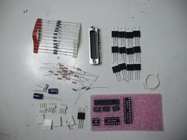
Parts & Supplies
Notice 6/21/12: Get A free 3-Month Instructables Membership Code with the purchase of a CNC Kit with a driver, motors, wire, and resistors. Limited Codes Available. Find it Here
Layout all the Parts:
– PIC16f870 – DIP or a PIC16F876A(must use a different firmware)
– Printed Circuit Board or strip board
– 20 mhz series oscillator, a regular one could be subed, just need to add 2x 22pf caps to gnd
– 12x logic level MOSFETs TO-220 package, i chose IRL630A or RFP12N10L or FDP8878
– 12x 1kohm 1/4w resistors – Brown – Black – Red
– 8x 10k ohm 1/4w resistors – Brown – Black – Orange
– 6x 500 ohm 1/4 resistors
– 12x 1n4004 or better
– Right-Angle Male DB-25
– 1x 7805 Voltage Regulator
– 2x 10uF Capacitor
– 1x 1uF Capacitor
– 3x LTV-827 OptoCoupler or Equiv.
– 1x 28 pin DIP socket
– 1x 8 pin DIP Socket
– 1x 16 pin DIP socket
A Full kit with all the Components, PIC Micro, and PCB Can Be Purchased
or Get a CNC Machine Kit with Driver, Motors, Power Resistors and Wire, It can Be found Here
Optional:
– 4x 4 Pin header
– 4x 4 pin housing
– 1x 2 pin header
– 1x 2 pin housing
– 18 crimps
Notes: Male and
Female DB-25 have different pin outs, and can not be substituted.
Tools:
– Soldering Iron
– Volt Meter/Continuity Tester
– Needle Nose Pliers
Check http://www.chromationsystems.com/partexplain.html Info
Additionally, a power supply will be required. To calculate power supply requirements: Motor Voltage/Motor Coil Resistance = amperage per coil. When full stepping each motor will have 2 coils/phases on at a time so minimum requirement is 6 * amp per coil. Then always use a power supply rated for %150 – %200 higher than the minimum. Switched mode PSUs will work, but will perform extremely bad compared to a capable linear power supply. Linear power supply’s can be identified by a large transformer and capacitor probably along with some circuitry, they are more expensive but worth it if you want a nice machine.
Step 2
Resistors and Diodes
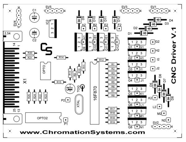
R1 – R12 are 1kohm 1/4w
R13 – R19 are 10kohm 1/4w
R20 – R25 are ~500 ohm 1/4w
TOG is a 10kohm 1/4w
D1 – D12 are 1n4004 or better
Place all the resistors and solder them in. Diagram Below
TOG is a 10kohm 1/4w resistor, mounted vertically.
Diodes D1 – D12 are next. Save the extra lead clippings for the jumpers.
These clamp the back EMF, protecting the PSU and logic.
Step 3
Jumpers, Oscillator and Sockets
Jumper points A – P need to be jumped.
( there is no jumpers O, I forgot about it)
Points labeled 1 are jumped to points labeled 2.
Example:
A1 goes to A2
B1 goes to B2
Ect.
Take a look at the diagrams below.
Take a lead clipping from the diodes (which is plenty thick)
Using a needle nose pliers bend the wire into a U shape large enough to bridge the gap.
When placing the jumpers ensure that you keep them away from any other holes or components.
Next Place the Oscillator in the XTAL, it goes in either way.
Make sure this gets a good shiny solder joint.
Sockets are Next
The 14 and 16 pin socket go in as pictured, line the notch on the socket up with the notch on the illustration.
Its not completely necessary but pin 6 on the 28-pin socket (RA4 on the PIC) (see image) should be removed, as there is a positive supply rail routed through it. And make sure to fill in its solder pad and hole with solder.
Then carefully line up all the pins into the holes and push down gently, watching to make sure no pins get flattened.
Step 4
Capacitors, Headers, DB-25
C1 & C2 are 10uF Electrolytic
C3 is a 1uF Electrolytic
Capacitors first, these are polarized so they need to go in correctly.
The white stripe down one side of the capacitor is the negative pin.
In the top-side illustration the black half is the negative side.
*also shown in the image notes below.
Headers SV1 – SV5 are next.
If you are using locking headers consider what way you need the lock part facing.
Otherwise they can go in however.
SV1 is the Y axis motor
SV2 is the X axis motor
SV3 is the Z axis motor
SV4, pin 1&2 is Negative Supply
SV4, pin 3&4 is Positive Supply
SV5 is positive supply for the motors
The right angle, male, DB-25 port is last for this step.
*note: A female port will not work as the pinout is different. If you want to use a female port or a panel mount port, use some solid strand wire to run from the port to the PCB.
A right angle port can be kinda of tricky to get in, but get a thin piece of metal, a tweezers or nail, to pry and direct pins into their holes. Only pins 2-7 and 18-25 are used, so the other ones could be clipped off to make the placement easier.
Keep it flush with the PCB, nice and tight or later plugging and unplugging will damage on the connections. Then solder a few pins to keep it in place.
Flare out the mounting pins as pictured below, and solder.
Finish up the rest of the pins, remembering only pins 2-7 and 18-25 need to be soldered, the rest don’t.
For more detail: Parallel Port 3 Axis CNC Driver, Opto-Isolated, Unipolar Steppers using PIC16F876A microcontroller


