Summary of DHT11 Low Cost Humidity Sensor using PIC16F628A with Proteus Simulation
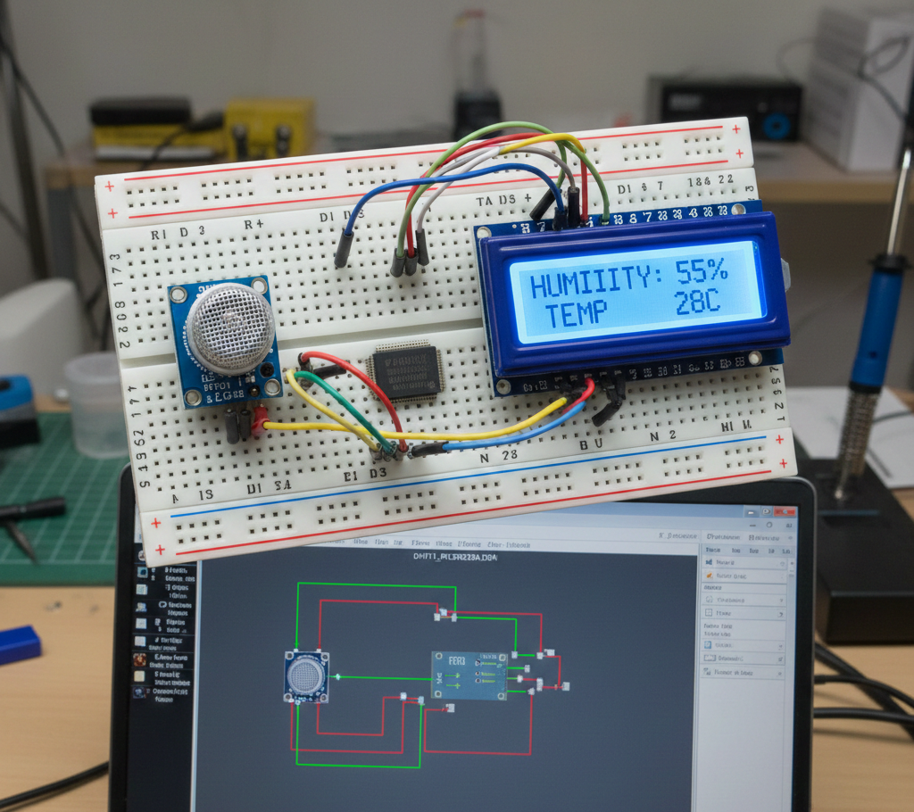
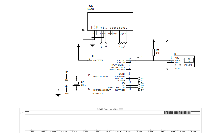
This project shows interfacing a DHT11 temperature and humidity sensor with a PIC16F628A in Proteus VSM. The PIC sends a start pulse on RA0, uses Timer2 to measure DHT11 pulse widths, reads five data bytes, verifies checksum, and displays temperature and humidity on a 16×2 LCD every second. The setup is suitable for educational labs, DIY monitoring, and prototyping.
Parts used in the DHT11 Low Cost Humidity Sensor using PIC16F628A with Proteus Simulation:
- PIC16F628A microcontroller
- DHT11 temperature & humidity sensor
- 16×2 LCD (LM016L)
- 4 MHz crystal oscillator
- 22 pF capacitors (for oscillator)
- 4.7 kΩ pull-up resistor
- Power supply (VDD / GND)
- How does the PIC communicate with the DHT11 sensor?
The PIC uses a single digital data line on RA0, sending a start signal and then reading timed pulses from the DHT11. - Why is Timer2 used in this project?
Timer2 measures pulse widths from the DHT11 to distinguish between logic 0 and 1. - Can this code run on real hardware?
Yes, the same firmware works on physical PIC16F628A hardware according to the article. - Why is a pull-up resistor required on the data line?
The DHT11 uses an open-drain output and requires a pull-up resistor for correct logic levels. - What causes No response from the sensor?
Incorrect timing, wiring issues, or a missing pull-up resistor can cause no response. - Can another PIC16 device be used for this project?
Yes, another PIC16 device can be used with minor pin and configuration changes. - Why is checksum verification important?
Checksum verification ensures the received temperature and humidity data is valid. - How often does the sensor update in this firmware?
The firmware reads data once every second.