Summary of An Integrated Approach to Developing Applications with Microchip PIC Microcontrollers
The article presents the MPIC development framework for PIC microcontroller education and prototyping, detailing its V-diagram design cycle, modular main board, ICSP-compatible programmer, and various plug-in modules. It emphasizes open, low-cost, single-sided PCB designs, freely available software tools (compilers, MPLAB, Simulink, Scilab/Scicos, Flowcode), and uses in secondary and university courses. The framework supports iterative prototyping (simulation, general prototyping, on-target prototyping) and testing (SIL, PIL, HIL), aiming to narrow development time and costs while enabling students and hobbyists to fabricate and extend the system safely.
Parts used in the MPIC development system:
- 40-pin Textool socket (main board)
- Microcontroller (PIC family, PDIP up to 40 pins)
- Greatz bridge (full-wave bridge rectifier) for power supply
- 10-pin IDC connectors (for plug-in modules and programmer)
- Resistor chains for pull-up/pull-down configuration
- Jumpers/short-circuit connectors
- RC oscillator components
- Quartz crystal oscillator
- Reset circuit with push key
- Programmer board (JDM and P16PRO compatible)
- 74HCT367 high-speed CMOS IC (programmer)
- Transistors and Zener diodes (voltage adaptation in programmer)
- 100 mA limited power supply (programmer)
- Microchip compliant FCC connector (programmer)
- Plug-in module PortKEY (input key module)
- Plug-in module PortLED (LED output module)
- Plug-in module LCDa16 (2x16 character LCD)
- Plug-in module DS1820 (Dallas DS1820 temperature sensor)
- Adapters for different microcontroller pin arrangements
- Single-sided printed circuit boards (PCBs)
1. Introduction
In our daily lives, a variety of devices such as telephones, household appliances, and cars incorporate “smart” electronics, typically manifested as embedded systems. At their core, these systems involve a microcomputer designed to oversee specific processes within the application. Microcontrollers (μC) or digital signal processing (DSP) devices commonly serve as the central component of embedded systems. These microcomputers, integrated onto a single chip, encompass not only a central processing unit and memory but also include various application-specific peripherals like AD and DA converters, timers, and communication modules [1]. As the most extensively produced processing devices, microcontrollers play a pivotal role in electronic control systems. Given their relevance to a diverse range of potential consumers, microcontrollers emerge as particularly noteworthy products.
Today, a variety of devices integrated into our daily routines, such as phones, household appliances, and cars, feature “smart” electronics, typically manifested as embedded systems. At their core, these systems consist of microcomputers designed to control specific processes within the application. Frequently, microcontrollers (μC) or digital signal processing (DSP) devices serve as the central components of embedded systems. These microcomputers, integrated onto a single chip, include not only a central processing unit and memory but also various application-dependent peripherals like AD and DA converters, timers, and communication modules [1].
Microcontrollers, being the most extensively manufactured processing devices, hold a crucial role in electronic control systems and are of interest not only in electrical but also in mechanical and industrial engineering for a broad range of potential consumers. As components become more intricate, the significance of a design methodology and the ability to easily test and verify the system on a tangible object become increasingly vital. The construction of application prototypes, whether in hardware or software, is thus a significant aspect of the design process. Since microcontroller-based application design involves a combination of computer programming and the construction of digital circuits [2], proficiency in both domains is essential. As technology rapidly advances, progress in this field must also be reflected in educational processes [3, 4]. Educational institutions, tasked with equipping students with relevant skills and knowledge, must stay attuned to industry needs and practices. Conversely, the industry bears the responsibility of communicating its specifics and requirements [5, 6].
2. Embedded system design cycle
As the complexity of embedded systems has seen a significant increase in recent decades, developers are encountering greater challenges in ensuring the competitiveness of their products in the market [8]. In light of this, the adoption of systematic design methods becomes imperative to effectively balance technical, cost, and time-to-market feasibility factors, rather than making compromises [5, 9].
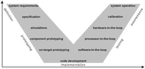
Typically, the design cycle follows a V-diagram representation, with various versions found in the literature, particularly in the context of embedded systems design [5]. Illustrated in Fig. 1, the general progression of design steps over time is depicted from left to right. Although the horizontal axis signifies time, the iterative nature of the design process often leads to cycling between the left and right legs of the diagram rather than a linear progression [10]. On the vertical axis, the level of system components’ abstraction is represented, with higher steps indicating a high-level system view and lower steps representing more detailed, low-level processes.
The design initiates with the specification of system requirements, which are then processed and decomposed along the left leg of the V-diagram into smaller components. At the bottom of the V-diagram lies the implementation stage, where the transition from decomposition to recomposition occurs, moving up along the right leg of the V-diagram. Here, the system’s entities are combined back into larger pieces, resulting in a fully assembled system. The ultimate goal of each design process is a system that operates according to specifications, with the V-diagram kept as narrow as possible to reduce design time and, consequently, costs [10].
The framework proposed in this paper aims to narrow the V-diagram for embedded system design by offering a common set of tools utilized throughout prototyping, implementation, and testing stages. In the prototyping stage, a simulation model is first designed to meet the requirements. For feasibility validation, design components are then prototyped on general prototyping hardware, without modeling timing characteristics at this stage, recognizing that they may change in the actual design. Once components behave appropriately, on-target prototyping is employed on the intended processing device, such as a microcontroller. This step validates characteristics like code compiler, fixed-point precision effects, and interactions among system components. Upon successful simulations and prototyping, a highly optimized code is generated in the implementation stage. Finally, in the testing stage, the design is evaluated while moving up along the right leg of the V-diagram, employing configurations like software-in-the-loop, processor-in-the-loop, and hardware-in-the-loop in successive steps [8].
3 MPIC development system
The objective of the MPICds [7] is not to rival commercially available platforms; instead, it aims to effectively integrate freely accessible tools and easily obtainable components. Similarly, as an educational tool akin to E-blocks [11] or MILES [12], the system is not tailored to a specific curriculum but can be easily adapted for use in various secondary school or university courses. Its modular concept makes it particularly suitable for self-learning, allowing the construction of components as needed, thereby reducing the overall system cost.
In the following subsections, we provide a more detailed description of the assumptions considered during the design of the MPICds and its key hardware components.
Design assumptions
Available on the market at relatively affordable prices, we have the option to select from a diverse array of quality development and programming supporting tools, some of which are freely accessible. Additionally, the firmware transfer can always be executed using the same interface. These features contribute to their popularity not only in professional settings but also in hobby electronics, making them a viable option for educational equipment. The following assumptions and limitations were considered during the design of the MPIC development system:
– Given that software development for the application typically involves an acyclic process of writing and testing program code, it is crucial to support the downloading of the code to a microcontroller and its subsequent verification.
– The system must be organized in a modular fashion to ensure maximum flexibility and facilitate rapid prototyping.
– Avoidance of pre-programmed chips in the design.
– All essential accompanying software tools should be freely accessible on the Internet.
– Microcontroller selection is limited to those supporting firmware transfer through the In-Circuit Serial Programming (ICSP) module, a property shared by the majority of PIC microcontrollers [15].
– Further restrictions on microcontroller selection are imposed, limiting choices to those available in the PDIP package types [15].
– The programmer must provide the capability to download firmware from a PC to the microcontroller using either a parallel (LPT) or serial (COM) port.
– The programmer should be designed to be permanently connected to the main board during programming or application runtime.
– All microcontroller I/O pins must be easily accessible on the main board plug-in module connectors.
– All printed circuit boards (PCB) should be single-sided to facilitate easy fabrication by potential users.
– For cases where the setting of the microcontroller’s operation using external signals is necessary, accessibility through jumpers or short-circuit connections is required.
– Plug-in modules must be designed to prevent harm to the system’s components even in the case of incorrect use.
These assumptions are rooted in an understanding of the challenges and difficulties often encountered by beginners in the field of microcontrollers. Consequently, while the system may not represent the most efficient variant, it is designed to provide users with a comprehensive understanding of the entire design cycle.
Main board
The central component of the development system is the main board, which houses the microcontroller and serves as the hub for all other system elements, including the power source, programmer, and plug-in modules, as needed. The electrical schematic is illustrated in Fig. 2.
The microcontroller is affixed to the main board via a standard 40-pin Textool socket. The decision to limit the microcontrollers to those with up to 40 pins is based on the fact that a 40-pin package represents the largest PDIP package type for PIC microcontrollers. Additionally, a more commonly used pin arrangement was prioritized, and adapters were designed for microcontrollers with different arrangements or lower pin counts. These adapters connect to the Textool socket in place of a 40-pin microcontroller.
The main board incorporates a power supply with a Greatz bridge, serving a dual purpose. Firstly, it functions as a classical full-wave bridge, allowing the input voltage to be either AC or DC. Secondly, it safeguards the connected power supply in cases where the programmer has its own power supply. Connection to the main board for plug-in modules and the programmer is facilitated through 10-pin IDC connectors. Each IDC connector provides one microcontroller port with the supply voltage for plug-in module connection. On the IDC connector of the PORTE, additional access is provided to the microcontroller’s pins for an external reset circuit, external oscillator, and external AD converter supply voltage. Each microcontroller port is linked to a resistor chain, configurable for either pull-up or pull-down functions through appropriate jumper connections.
The IDC connector for the programmer attachment offers all necessary pins for connecting ICSP-compatible programmers. Additionally, the remaining pins on this connector provide access to the microcontroller’s USART module pins, which can be utilized during firmware download using bootloaders. The programmer’s virtual connection-disconnection to the microcontroller is manually controlled by a single switch.
Spaces for the RC and quartz crystal oscillator are designated on the printed circuit board. A simple reset circuit, featuring a key as an execution unit, is also incorporated to ensure it does not interfere with the ICSP programmer’s activity.
Programmer
Three key design assumptions were considered in the development of the programmer’s hardware component. These include the requirement that microcontrollers must be programmable in the ICSP mode, the firmware download should be achievable using either a serial or parallel PC port, and the accompanying software programming tools should be freely accessible on the Internet. As a result, the programmer is designed to be compatible with JDM [16] and P16PRO [17] programmers. For the JDM programmer, firmware download is accomplished using the COM port, while the P16PRO utilizes the LPT port. ICSP, a synchronous procedure specified by Microchip for programming PIC microcontrollers [18], employs five or six microcontroller pins for writing and reading the firmware. The sixth pin is only driven in microcontrollers that can also be programmed using the Low-Voltage ICSP procedure.
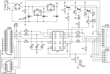
The electrical schematic of the programmer is illustrated in Fig. 3, consisting solely of standard elements and connectable to the main board using an IDC connector cable. Similar to the main board, the programmer has its own power supply for two main reasons. Firstly, to safeguard the microcontroller against damages during programming, featuring a built-in 100 mA current limit. Secondly, it allows for autonomous use, such as programming a microcontroller already attached to the end application. For such cases, a Microchip compliant FCC connector is provided on the printed circuit board.
The primary element bridging the PC and microcontroller in the programmer is the high-speed CMOS integrated circuit 74HCT367. This IC contains six three-state non-inverting buffers, controlled by two enable inputs, facilitating the transmission of firmware between the PC and microcontroller. The circuit also incorporates other elements, including transistors and Zener diodes, which play a role in adapting the COM port voltage levels—unlike the LPT port, the COM port is not TTL compatible. The transistors are employed to ensure appropriate current loads or to convert voltage levels, crucial in the ICSP programming mode where voltages higher than 5 V need to be generated.
Plug-in modules
To facilitate the testing and validation of programs programmed into microcontrollers, a series of fundamental test circuits has been created. These circuits, referred to as plug-in modules, are connected to the main board for each specific application design. Some of these modules include:
– PortKEY: A module designed to manipulate the state of a particular microcontroller’s input using a key.
– PortLED: A module utilized to represent a specific microcontroller’s output by illuminating an LED.
– LCDa16: An LCD module featuring two 16-character alphanumeric lines.
– DS1820: A module equipped with a Dallas DS1820 temperature sensor.
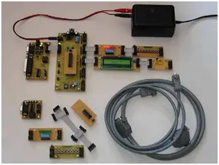
To provide maximum flexibility in usage, the modules are designed so that their final functions can be customized by configuring jumpers or short-circuit connections. An example of a fabricated development system is depicted in Fig. 4. A more detailed description of each component within the system can be found in [7], along with the electrical schematic and suggested printed circuit board design.
4. Software tools
In the development of microcontroller-based applications, a variety of software tools are employed. When dealing with the PIC microcontroller family, there is a diverse selection of high-quality software tools available from various manufacturers. Many of these tools, including some from Microchip, offer their full functionality for free on the Internet. Broadly, these tools can be categorized into development tools, which process the source code, and programming tools, which are utilized to transfer the compiled firmware from a PC to the microcontroller.
Development tools
Microchip provides a comprehensive set of development tools for its PIC microcontroller family. This encompasses an integrated development environment (IDE) commonly known as MPLAB [19], incorporating features such as an assembler, C compiler, simulator, product selector guide, and more. While these tools are integrated, Microchip’s proprietary hardware is typically the main focus of the programming tools associated with them. Therefore, the following subsection introduces alternative software tools specifically intended for use with our MPICds programmer.
In addition to Microchip’s development tools, developers have the option to choose from tools offered by other manufacturers. These tools typically include compilers for higher-level languages such as C, Basic, and Pascal, real-time operating systems, and tools adapted for operating systems other than Microsoft Windows (e.g., Linux). Noteworthy among the higher-level language compilers are HI-TECH PICC [20], IAR Embedded Workbench [21], CCS C [23], and mikroC [23] C language compilers. These compilers offer a comprehensive set of common and microcontroller-specific libraries, including preprocessor commands and peripheral drivers. They can be used either with their own integrated development environments or integrated with Microchip’s MPLAB IDE. While mikroC is limited to developing code for 8-bit microcontrollers (PIC10, PIC12, PIC14, PIC16, and PIC18 families), HI-TECH, IAR, and CCS C tools also cover 16-bit microcontrollers (dsPIC and PIC24 families).
Traditional code development tools, like those mentioned above, typically occur late in the design cycle during the implementation and test stages. This late integration of hardware and software can make the design process more susceptible to errors [5]. The availability of real-time prototyping hardware, such as MPICds for PIC microcontrollers, allows for addressing implementation aspects earlier in the design cycle. This approach supplements traditional prototyping methods, like offline simulations, with real testing [4, 10].
Model-based design tools have recently emerged, allowing developers to design simulation models in the early stages of the design process and then verify them on real hardware through automatic code generation. These tools are used not only in the prototyping stage but also in the implementation and testing stages, where extensive code generation for different hardware configurations is required [5, 8]. Some tools following the model-based design paradigm, suitable for use with PIC microcontrollers, are described below.
One widely used model-based design tool is The MathWorks’ Simulink platform [24]. It provides an interactive graphical environment where algorithms are developed in the form of block diagrams. With the help of Real-Time Workshop Embedded Coder, it can generate target-independent ANSI C code. Microchip’s MPLAB IDE plug-in for MATLAB and Simulink allows developers to include Simulink models in the design of 16-bit microcontroller applications, with automatically generated code seamlessly integrated into MPLAB IDE projects.
Another tool, extending the functionalities of Simulink, is the Embedded Target for 16 bits PIC [25]. It provides blocks for microcontroller-specific peripherals such as ADC converters, UART and SPI communication, PWM modulation, etc. Models developed with this tool can be compiled and built for 16-bit microcontrollers directly from Simulink without requiring MPLAB IDE.
In the realm of open-source tools, Evidence’s Scilab/Scicos Code Generator for FLEX [26] has emerged as a model-based design platform. Similar to Octave, Scilab [27] is an open-source platform for numerical computation, and Scicos [28] is its block diagram modeler and simulator, akin to Simulink. Using the built-in code generator, Scicos block diagrams can be exported to ERIKA Enterprise [26] and run on the FLEX board for dsPIC microcontrollers [26]. Although these open-source model-based design tools are still in the early development stage, they merit mention as they aim to cover the entire design cycle.
The last tool in the group of model-based design tools is Flowcode from Matrix Multimedia [11]. It supports simulation and the transfer of program code to a subset of 8-bit microcontrollers, with code generated from flowchart-type block diagrams.
Programming tools
The hardware component of the MPIC development system can be complemented by utilizing one of the following freely available software programming tools:
– IC-Prog [29]: This tool is suitable for programming the microcontroller through the PC’s COM port when the programmer is in JDM compatible mode.
– PICALL [17]: Designed for programming using the PC’s LPT port and the programmer in P16PRO compatible mode.
– WinPic [30]: A fully customizable programmer that allows the programming of the microcontroller using either the serial or parallel port.
Details regarding the configuration settings for the proper operation of these programs with the presented programmer hardware can be found in [7].
5. Frame work as an educational tool
If, during the framework design, all the predefined assumptions of MPICds were met and efficient supporting software tools were chosen, the resulting development system is a robust piece of equipment suitable for educational purposes. It can be utilized in secondary schools or university courses, not limited to electrical engineering education. Its modular hardware and versatile software tools make it adaptable to various engineering branches, eliminating the need for extensive programming skills. Additionally, the framework is efficient enough to cater to experts designing microcontroller-based applications.
In engineering education, the use of models for problem-solving is a defining characteristic. Various graphical representations, such as circuit schematics for hardware and different forms of block diagrams for software execution flow, are essential. Drawing parallels between the product design cycle and the educational process, where specific topics need to be covered theoretically and practically within a limited time frame, similar challenges arise. Efficient development tools play a crucial role in overcoming these challenges. The framework contributes to the educational process by allowing students to build hardware models by connecting the microcontroller with MPICds plug-in modules. It enables an easy transition from high-level models to efficient product implementations using contemporary software tools.
In secondary school courses, the framework can serve as common supporting educational equipment for multiple subjects. It can be utilized in courses covering the basics of microprocessors and microcontrollers, their programming (in assembler, higher-level language, or through models with automatically generated code), and in courses related to the design of additional plug-in modules. Motivated students may even fabricate the system or its specific parts on their own.
At the university level, the framework becomes educational equipment for courses focusing on microprocessors, microcontrollers, or embedded systems. It covers both programming and hardware peripheral design support. Given the increasing demand for interdisciplinary education, the system is also an attractive solution for students in other engineering sciences such as computer, mechanical, chemical, or industrial engineering. Subjects that the system can assist in covering include computer architectures, digital signal processing, mechatronics, automated measuring, and more.
6. Conclusion
This paper introduces the framework, which comprises the MPIC development system and supporting software tools, along with suggestions for its incorporation into educational courses. Tailored for Microchip’s PIC microcontroller application design, the MPICds is intentionally designed with openness, allowing individuals to independently fabricate and use it with freely available basic accompanying software. Its design is intentionally general, making it suitable for use either as a complete system or as a component within another system. It does not specifically target a particular microcontroller device, offering the flexibility to choose the most suitable device for each application design. When used as a complete system, the MPICds stands as a robust system where even incorrect usage does not compromise any of its components. The ongoing development and enhancement of the system include the design of additional plug-in modules such as a matrix keyboard, 7-segment LED display, stepper motor module, IR communication module, and more. Consequently, the system proves particularly suitable for educational purposes, aiming to provide support for those venturing into the realm of microcontrollers.
- What is the main objective of the MPIC development system?
The objective is to integrate freely accessible tools and easily obtainable components into a modular, low-cost educational development system for PIC microcontrollers. - Can the MPIC programmer use serial and parallel PC ports?
Yes; it is compatible with JDM mode using the COM port and P16PRO mode using the LPT port. - Does the main board support different microcontrollers?
Yes; it uses a 40-pin Textool socket and adapters for microcontrollers with different arrangements or lower pin counts, limited to PDIP packages up to 40 pins. - What protections are included for safe usage?
The design avoids pre-programmed chips, uses single-sided PCBs, includes jumper protections, and the programmer has a 100 mA current limit to protect the microcontroller during programming. - How are plug-in modules connected to the system?
Plug-in modules connect via 10-pin IDC connectors, each providing a microcontroller port with supply voltage and configurable signals through jumpers. - What software tools are suggested for development?
Suggested tools include Microchip MPLAB, HI-TECH PICC, IAR Embedded Workbench, CCS C, mikroC, Simulink with Embedded Coder, Scilab/Scicos code generator, Flowcode, and programming tools IC-Prog, PICALL, and WinPic. - Can the system be fabricated by students?
Yes; the system is designed to be fabricated by users, with single-sided PCB designs and openly available schematics. - Does the framework support early-stage prototyping and testing?
Yes; it supports simulation, general prototyping, on-target prototyping, and testing configurations like SIL, PIL, and HIL to narrow the V-diagram. - Is the MPICds tailored to a specific curriculum?
No; it is general and modular, adaptable to various secondary school or university courses and multiple engineering disciplines. - What additional plug-in modules are being developed?
Planned modules include a matrix keyboard, 7-segment LED display, stepper motor module, and IR communication module.