Spectrum Analyzer using TMS320F28023DA with Proteus Simulation

Summary of Spectrum Analyzer using TMS320F28023DA with Proteus Simulation


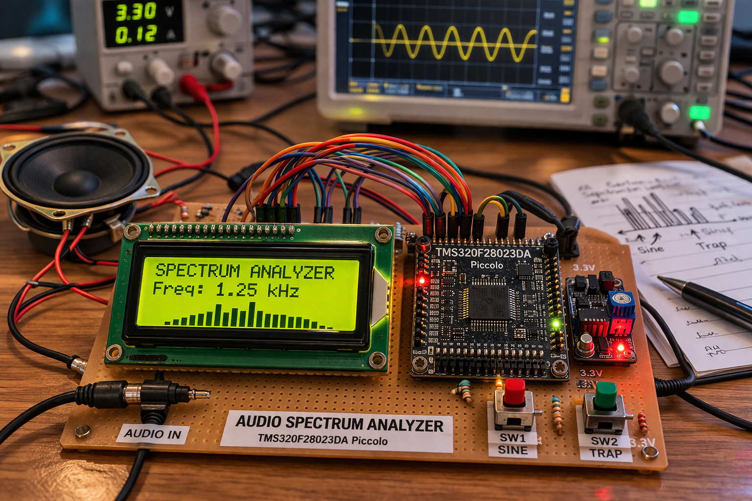
This project implements a real-time audio spectrum analyzer using the TMS320F28023DA Piccolo microcontroller, simulated in Proteus VSM. It captures analog audio signals via ADC, processes frequency data using embedded DSP capabilities, and visualizes results on a 16x2 LCD. The system supports multiple input waveforms through switches, demonstrating practical integration of signal conditioning, digital processing, and display control for educational and diagnostic applications.

Parts used in the Spectrum Analyzer using TMS320F28023DA:

  • TMS320F28023DA (Piccolo MCU)
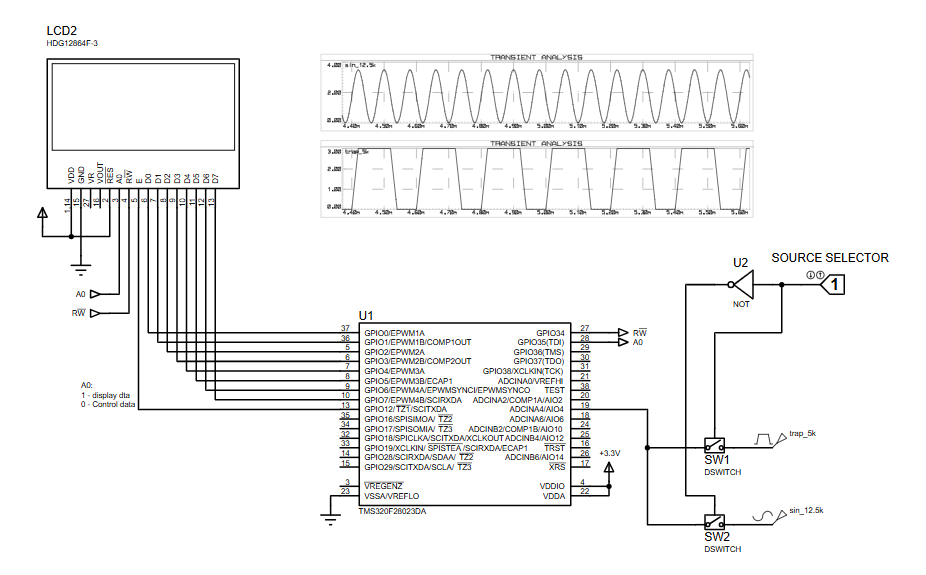
  • 16x2 LCD (HD44780 compatible)
  • Analog signal sources (sine, trapezoidal)
  • Switches (SW1, SW2) for source selection
  • Logic inverter (NOT gate)
  • Power supply (+3.3V)
  • Passive components (wiring, grounding)

Introduction

This project demonstrates a real-time audio spectrum analyzer using the TMS320F28023DA Piccolo microcontroller, simulated in Proteus VSM. The system captures an audio signal, processes it using embedded DSP capabilities, and displays the frequency characteristics on an LCD.

It’s a great example of a microcontroller project combining embedded systems, signal processing, and practical electronics. Spectrum analyzers are widely used in audio engineering, diagnostics, and signal analysis, making this project both educational and highly practical.

Audio spectrum analyzer microcontroller project hardware setup
Illustrative View of the Concept.

How the Project Works (Overview)

The system takes an input audio signal (sine/trap waveform in simulation), converts it into digital data using the microcontroller’s ADC, and processes it to extract frequency information.

The processed data is then displayed on a 16×2 LCD, showing signal characteristics. A source selector switch allows switching between different input signals, making it easy to observe how the spectrum changes in real time.

Workflow Explanation

Signal Flow:

  1. Audio Input Source (SW1 / SW2)
    • Select between different waveform inputs (e.g., sine or trapezoidal)
  2. Signal Conditioning
    • Input routed to ADC channel of the microcontroller
  3. ADC Conversion (TMS320F28023DA)
    • Analog signal → digital samples
  4. Digital Signal Processing
    • Frequency analysis (likely FFT or sampling-based approximation)
  5. LCD Display (16×2)
    • Displays processed output (frequency/amplitude info)
  6. Control Signals
    • GPIO pins manage LCD data and control lines

Key Features

  • Real-time audio signal analysis
  • Uses DSP-enabled Piccolo microcontroller
  • Multiple input signal selection via switches
  • LCD-based output visualization
  • Simulated entirely in Proteus VSM
  • Demonstrates ADC + signal processing + display integration
  • Suitable for learning embedded DSP concepts

Components Used

  • TMS320F28023DA (Piccolo MCU)
  • 16×2 LCD (HD44780 compatible)
  • Analog signal sources (sine, trapezoidal)
  • Switches (SW1, SW2) for source selection
  • Logic inverter (NOT gate)
  • Power supply (+3.3V)
  • Passive components (wiring, grounding)

Applications

  • Audio signal analysis tools
  • Noise and frequency diagnostics
  • Educational DSP demonstrations
  • Embedded systems training projects
  • DIY electronics for sound visualization
  • Basic spectrum monitoring systems

Explanation of Code (High-Level)

The firmware (developed in Code Composer Studio for Piccolo) is responsible for:

  • ADC Module
    • Samples incoming analog signal at a defined rate
  • Signal Processing
    • Performs frequency analysis (likely FFT or sampling-based estimation)
  • GPIO Control
    • Drives LCD control pins (RS, RW, EN)
  • Display Handling
    • Sends processed data to LCD for visualization
  • Input Handling
    • Reads selected signal source via switches
  • Timing / Sampling
    • Uses timers to ensure consistent sampling frequency

Source Code

struct PAGE
 { char data[MAX_COLUMNS];
 };

#define FONT_WIDTH   4
#define FONT_HEIGHT  6

#define K_INDEX      10    // index of 'k' char
#define DOT_INDEX    11    // index of '.' char
const char digits_top[] = {0x69, 0x26, 0x69, 0x79, 0x26, 0xE8, 0x68, 0xF1, 0x69, 0x69, 0x89, 0x00};
const char digits_mid[] = {0x99, 0x22, 0x16, 0x21, 0xAF, 0xE1, 0xE9, 0x12, 0x69, 0x97, 0xAC, 0x00};
const char digits_btm[] = {0x96, 0x2F, 0x8F, 0x96, 0x22, 0x1E, 0x96, 0x48, 0x96, 0x16, 0xA9, 0x66}; 

Proteus Simulation

This spectrum analyzer project using the TMS320F28023DA is a solid example of combining embedded systems, DSP, and Proteus simulation into a practical application. It helps you understand how real-world audio signals are processed inside a microcontroller.

A great hands-on project for anyone exploring microcontroller projects, signal processing, and DIY electronics.

Conclusion

This spectrum analyzer project using the TMS320F28023DA is a solid example of combining embedded systems, DSP, and Proteus simulation into a practical application. It helps you understand how real-world audio signals are processed inside a microcontroller.

This Audio Spectrum Analyzer using TMS320F28023DA is a great hands-on project for learning embedded systems, DSP, and Proteus simulation in a practical way.

Quick Solutions to Questions related to Spectrum Analyzer using TMS320F28023DA:

  • What is the primary function of this project?
    The project demonstrates a real-time audio spectrum analyzer that captures audio signals, processes them using DSP, and displays frequency characteristics on an LCD.
  • How does the system convert analog signals to digital data?
    The microcontroller uses its ADC module to convert the incoming analog audio signal into digital samples.
  • Can users switch between different input signals?
    Yes, a source selector switch allows switching between different waveform inputs like sine or trapezoidal waves.
  • Which software is used to develop the firmware?
    The firmware is developed using Code Composer Studio specifically for the Piccolo microcontroller.
  • What simulation environment is used for this project?
    The entire system is simulated entirely in Proteus VSM.
  • Does the code handle timing for sampling?
    Yes, the firmware uses timers to ensure a consistent sampling frequency during signal acquisition.
  • What type of display is utilized in the circuit?
    A 16x2 LCD compatible with the HD44780 controller is used to show processed output.
  • What are the main applications of this device?
    Applications include audio signal analysis tools, noise diagnostics, educational DSP demonstrations, and DIY sound visualization.

About The Author

Ibrar Ayyub

I am an experienced technical writer holding a Master's degree in computer science from BZU Multan, Pakistan University. With a background spanning various industries, particularly in home automation and engineering, I have honed my skills in crafting clear and concise content. Proficient in leveraging infographics and diagrams, I strive to simplify complex concepts for readers. My strength lies in thorough research and presenting information in a structured and logical format.

Follow Us:
LinkedinTwitter