What This Is
This project is for a small electronic unit that allows the user to sense the presence and relative signal strength of wireless hotspots. It can be worn as a pendant or carried in a pocket. It is “always on” and communicates the presence and signal strength of an in-range hotspot by way of sequences of pulses – like a heartbeat you can feel. The stronger and faster the “heartbeat”, the stronger the wireless signal detected.
It does not actually authenticate or otherwise interact with a hotspot in any way. It is a 100% passive device, meaning it transmits nothing — it can detect hotspots, but cannot be detected itself.
How It Was Made
This project consists of a microcontroller, some custom interface electronics, a small vibe motor, and an off-the-shelf Wi-Fi detector – the one I used is by D-Link and is keychain-sized.
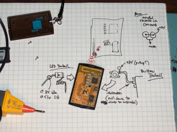
Here is the sensor I used, and some pictures of the construction. Details of the design will follow.
How It Works
The microcontroller periodically “presses” the button on the detector to initiate a reading. Then the microcontroller “reads” the output from the indicator LEDs on the detector, and uses this as the basis for pulsing out a signal on the vibe motor, which the wearer can feel.
In this way, the unit keeps you updated on the presence and signal strength of a wireless hotspot in your vicinity. No pulses means no signal. Short pulses means a weak signal. Faster, more frequent pulses means a stronger signal. This feedback is very much like a heartbeat, and is extremely intuitive to interpret.
How To Make Your Own
First of all, I use a microcontroller in this project. If you aren’t familiar with terms like 12F629 or .HEX files and how to blast them into a PIC, you will have trouble with this project.
The D-Link sensor I used works like this — press the button and the LEDs light up in a “scanning” pattern while it looks for a signal. It can be in this scanning pattern for up to a few seconds. Afterwards, it lights up either one, two, three, or four of the green LEDs to indicate relative signal strength. If there is no signal detected, a single red LED is lit. The LED(s) remain lit for a few seconds, then the sensor shuts off.
If your chosen sensor works differently, you will need to adjust the electronic interface and the program in the microcontroller accordingly.
For more detail: Build your own Wireless Network detector using PIC12F629


