
Summary of Integrated Solar ChargeController, Inverter, PowerBank, Lamp
This project integrates a microcontroller-based PWM solar charge controller, square-wave inverter, USB power bank, and emergency LED lamp on one board, controlled via a two-button menu on a Nokia 5110 display. It uses an AVR Atmega microcontroller (Optiboot), MOSFETs for charging, load switching and inverter driving, a buck regulator for Li-ion charging, and supports up to 100 W solar panels and 12 V lead-acid batteries. Features include PWM charging, three DC load controls, USB power output, display backlight switch, and onboard Li-ion for independent lamp and power-bank operation.
Parts used in the Integrated Solar ChargeController, Inverter, PowerBank, Lamp:
- AVR Atmega8A microcontroller (or Atmega328P with minor changes)
- Nokia 5110 LCD display
- Two momentary touch buttons (scroll and select)
- Slide power on/off switch
- P-MOSFET for solar charging
- 2N2222 transistor for P-MOSFET driving
- N-MOSFETs for DC load control
- N-MOSFETs (two) for inverter driving
- Center-tapped step-up transformer for inverter
- Buck regulator module for Li-ion charging
- Li-ion (on-board) battery
- 12 V lead-acid battery (external)
- Solar PV panel (up to 100 W)
- Smoothing capacitors for switch debouncing
- MOSFETs shield / protoboard wiring and hot-glue insulation
- USB boost circuitry (power bank boost converter)
- Super-bright LED for emergency lamp
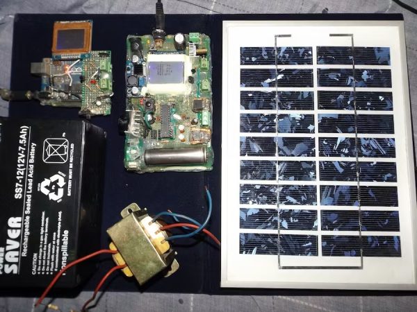
Microcontroller based Solar PV System’s charge controller, inverter, PowerBank & LED lamp with menu-based navigation system on LCD display.
Story
About this Project
I have a few solar panels, 12 Volt batteries, transformers and few more stuff laying around for a while crying out aloud to make some good use of them. Thus the birth of this device – complete small PV solution on a single board. Lets review first which does what, shall we?
- A charge controller is a device which regulates the charging of DC storage/battery from a photovoltaic solar panel and discharging of the battery by the load to prolong battery life.
- An inverter is a device that converts DC form of electricity to AC form for operating AC Loads.
- Power Bank provides 5V DC supply through USB port to gadgets/mobile devices for portable charging or off-grid charging.
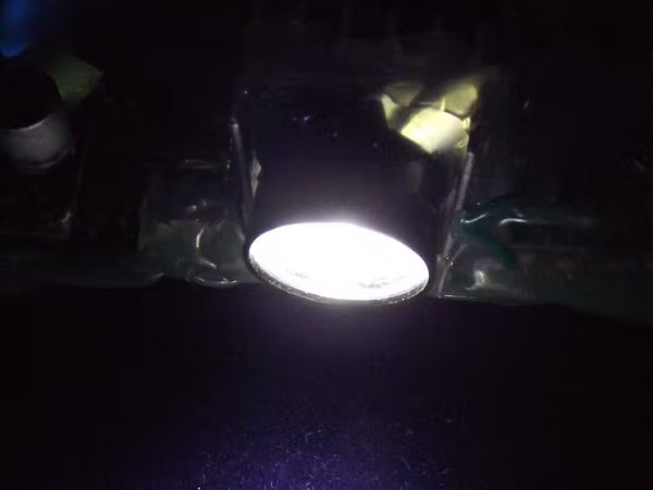
- Emergency lamp is a super bright LED light source which can be used during power outage, camping, outdoor activities after dusk.
This device I made has all these features, the last two features are supported independently by the on-board Li-ion battery. With a solar panel (up to 100 Watt), a 12 Volt lead acid battery and a transformer- all the options can be utilized.
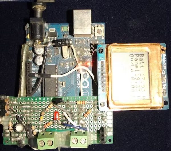
Proto Version on Uno
The first version was developed on Uno Board with minimum hardware and minimum options. The Nokia display was directly mounted and a MOSFETs shield was developed to support charging/discharging of the battery. There is no menu control, no inverter, no PWM charging and cool features! Just on/off charging and showing battery and panel voltage levels. Does the job but got no charm!
Full Fledged Version on Protoboard
Then I developed this new one with following features:
- PWM Solar Charge Controller up to 100 Watt Panel
- Square wave mini 60 Watt Inverter
- Up to three 12 Volts DC load control
- Primary DC load supports auto on/off features
- An independent USB Power Bank
- Buck regulator module
- Emergency on board LED Lamp with Blink and Brightness control
2 button/switch controlled scroll and select based menu for user control, displaying options and status information on the Nokia 5110 display. Very Cool! Back side is Hot-Glue Insulated for short circuit protection against metallic objects!
There are few more convenient features like on/off switch for display backlight, separating the buck for independent operation by switching off from the internal battery.
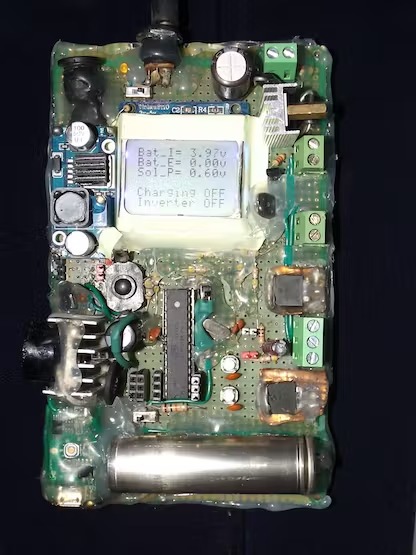
Accessing the menu on Nokia 5110 display with user button is shown here:
Let’s learn some technical stuff!
Charge controller can be On/Off, PWM or MPPT types. On/Off is the simplest form (my version 1 – picture above) of controller which does not throttle the charging current as the battery voltage approaches it full charge voltage.
Where as PWM gradually decreases the charging current as the battery gets full. PWM controller has following benefits:
- Helps recovering lost battery capacity and de-sulfate a battery
- Increases battery’s ability to accept more charge
- Maintain high average battery capacities up to 95%
- Equalize drifting battery cells, so internal cells can achieve same potential
- Reduce battery heating and gassing thus preventing electrolyte loss
- Slows down aging and prolong system life
PWM
But PWM can’t get most of the electrical power out of PV solar panels, because it drags the panel to operate near battery voltage. MPPT is the solution to this problem which basically is a DC to DC adjustable buck-boost converter, it can convert most of the solar power compared to PWM controller.
Inverters can be square wave, modified sine wave and pure sine wave types. Square wave inverter is very simple in design and good enough small DC loads like AC lamps, CFL lamps, table fans, soldering irons but not recommended for inductive motors, delicate equipments/power supplies because of harmonic distortion.
Modified sine wave is kind of retarded sine wave created form square waves, better than plain square wave inverters. Sine wave inverter are best for all types of load but complex to design hardware, difficult software algorithm to operate and expensive to make.
A buck regulator is a step down DC-DC converter, here I have used a buck module to charge the 4.2 V Li-ion battery that powers the controller (Arduino + display), independent USB power bank, on-board LED lamp.
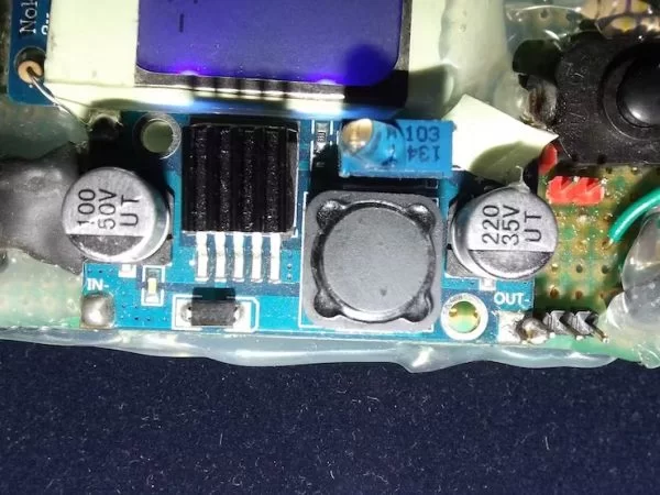
Now USB power bank basically is a DC-DC boost that can convert a range of voltages below 5 (like 3.3 to 4.2 volts range) from a Li-ion or LiPo battery to 5 volts which is the USB bus voltage that can charge mobile devices.
It also has a buck converter to charge that battery. In my project the buck module takes some juice from panel to charge the internal (on board) battery.
Workings of the Hardware
Before we go into details, check this image of everything connected around the device:
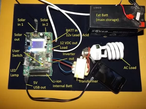
The system has various hardware for serving different purposes. Of course the brain is AVR Atmega8A microcontroller (can be used Atmega328P with minor changes, discussed below) which is programmed in Arduino.
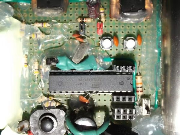
A fresh Atmega8A is burned with Arduino Optiboot8 bootloader, you may buy a Bootloaded Arduino Mini/Atmega328 to avoid the hassle.
The controller, display, LED lamp and power bank is powered from on board Li-ion battery. Two momentary touch buttons are for accessing the menu on display, which allows user to operate different functions of the device. The switches are hardware de-bounced through smoothing capacitors which are connected in parallel.
A slide switch allows to power up/shutdown the device as required.
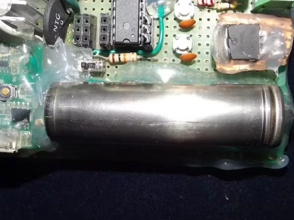
The solar charging function is performed by a P-MOSFET driven by 2N2222 transistor based driving circuit which is controlled through PWM from microcontroller. The PWM is controlled based on the external battery voltage level. Current from solar panels flows through P-MOSFET to the lead acid battery. When battery is fully charged the MOSFET is turned off from the microcontroller. After the charging is turned off, battery voltage starts to gradually fall, when it reaches 13.6 volt charging is resumed again with low duty cycle to maintain float charging.
The 12 Volt DC load is controlled through a N-MOSFET by controlling its Gate pin from the Microcontroller.
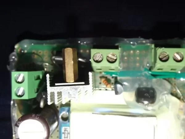
The on-board LED LAMP is also driven through a NMOS. The Gate of this MOSFET is PWM controlled for brightness adjustment of the LED.
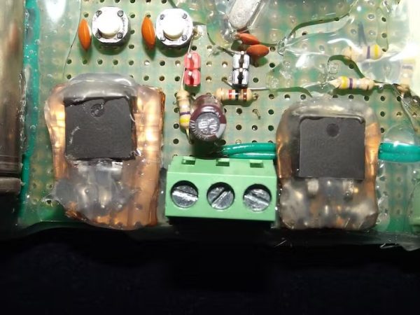
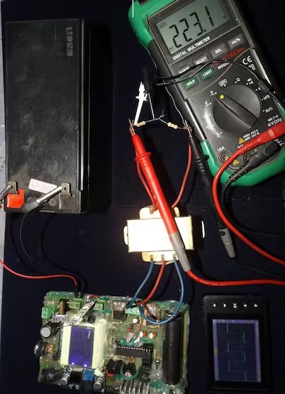
The inverter block is consist of 2 N-MOSFETs which are alternatively turned On/Off to simulate AC. By adding an external center tapped transformer, square wave AC supply can be realized.
Following figure explains the inverter action:
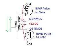
By allowing current to flow through the center tap of a step up transformer’s coil in opposite direction alternatively using MOSFETs, AC voltage in secondary can be created. This happens because when the top MOSFET is on and bottom MOSFET is off, current flows upward. But when the top MOSFET is off and the Bottom MOSFET is on, current flows downward.
Both the MOSFETs must be toggled at twice the frequency of AC. Check the next picture to understand it:
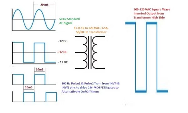
To create 50 Hz AC, an alternating Square Wave is applied on 12-0-12V/220V center tapped transformer’s low side. 50 Hz means 20 ms time for each wave.
That’s why 20ms/2 = 10 ms or 100 times Toggle the Gate Signals applied to the Transformer driving MOSFETs (inverter MOSFETs).
Warning !!! : AC Voltage is Lethal for Human, may cause death/injury ! Never touch HV side of transformer with bare hand !
If inverter function is not used, 2XDC Load option allows to use two more 12 volt DC loads at Inverter terminal.
- What microcontroller is used in this project?
The project uses an AVR Atmega8A microcontroller, and Atmega328P can be used with minor changes. - How is the solar charging implemented?
Solar charging is implemented using a P-MOSFET driven by a 2N2222 transistor and PWM from the microcontroller. - Can this system support MPPT charging?
The project describes PWM charging; MPPT is explained as a different approach but this build uses PWM. - What type of inverter does the project include?
The project includes a square wave mini inverter using two N-MOSFETs and a center-tapped transformer for AC output. - How is the on-board LED lamp controlled?
The LED lamp is driven by an N-MOSFET with PWM control for blink and brightness adjustment. - Does the device provide USB power?
Yes, an independent USB power bank function is provided using the on-board Li-ion battery and boost circuitry. - What display and user interface are used?
A Nokia 5110 display is used with two buttons for scroll and select based menu navigation. - How many 12 V DC loads can be controlled?
The system supports up to three 12 V DC load controls, with two additional loads available at the inverter terminal if inverter is unused. - What protects the board from shorting against metallic objects?
The back side is insulated with hot glue for short circuit protection. - How does the buck module function in this system?
The buck regulator charges the 4.2 V Li-ion battery that powers the controller, display, power bank, and LED lamp, and can be switched off for independent operation.
