Summary of PIC MICROCONTROLLER BASED USB STORAGE
Summary: This project implements USB protocol communication with a PIC18F4550 microcontroller to read/write packets of varying sizes. It includes multiple test cases (single/128 packet reads/writes and timeout handling), a Visual C# GUI with debugging, and firmware for the PIC. The report covers USB protocol/packet types, transfer types, descriptors, hardware components (PIC18F4550, 20 MHz Saronix oscillator, PICKit 2), oscillator/clock requirements, and hardware/software integration and programming.
Parts used in the USB Storage Project:
- PIC18F4550 microcontroller
- PICKit 2 programmer
- Saronix 20 MHz oscillator
- USB Type B connector
- USB cable (host connection)
- Computer running Visual C# GUI
- Power supply via USB (bus power)
- Crystal/capacitor components for oscillator configurations
INTRODUCTION
The primary objective of this project is to execute the USB protocol and manage the reading and writing of packets of various sizes within the memory of the Peripheral Interface Controller (PIC) microcontroller. Several test cases have been incorporated, which include:
– Writing a single packet to the device
– Reading and writing a single packet
– Writing a single packet followed by reading 128 packets
– Writing 128 packets and then reading a single packet
– Writing a single packet with a read timeout
This project involves a co-design approach encompassing both software and hardware components. The software component is developed using Visual C# and incorporates the creation of a Graphical User Interface (GUI) with debugging capabilities. On the other hand, the hardware aspect employs the PIC microcontroller 18F4550, PIC Kit 2, and a Saronix 20MHz oscillator. These hardware components are interconnected to the computer via the USB interface.
Chapter 2 of the report delves into the USB protocol, detailing the various packet types within the USB protocol. Additionally, it provides an explanation of different USB transfer types and USB descriptor fields.
Chapter 3 provides insights into the different hardware components of the design and also discusses the programming of the PIC 18F4550 using PICKit 2.
In Chapter 4, the emphasis is on the practical execution of the design. This chapter presents a block diagram of the design and delves into the considerations that must be addressed during the hardware implementation. Additionally, this chapter provides insights into the software development procedure and the creation of PIC18F4550 firmware.
Chapter 5, on the other hand, centers on summarizing the project’s findings and prospects for potential enhancements in the future.
UNIVERSAL SERIAL BUS
In this chapter, we delve into the USB protocol, covering aspects like the various packet types within it. The USB protocol comprises three distinct packet types. Furthermore, we explore diverse USB transfer types and the fields found in USB descriptors.
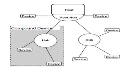
USB, an acronym for Universal Serial Bus, employs a tiered star topology, akin to the 10BaseT Ethernet cable. The tiered star topology is illustrated in Figure 2.1, showcasing a central hub controller as a key component. This hub controller serves the purpose of filtering transactions of different speeds, ensuring that low-speed devices do not receive high or full-speed transactions. It’s important to note that a USB bus can accommodate up to 127 devices.
The Universal Serial Bus (USB) possesses several outstanding attributes that render it the preferred choice for designers. Firstly, USB is known for its user-friendliness, requiring no complex configuration or setup. Moreover, it offers impressive speed without causing communication bottlenecks. In terms of reliability, USB interfaces are seldom prone to errors, featuring automatic retry mechanisms for error occurrences. Additionally, USB exhibits versatility, accommodating various types of peripherals. This cost-effective solution benefits both manufacturers and users, sparing them from exorbitant expenses.
Furthermore, USB stands out as an energy-efficient option, extensively utilized to conserve power and extend battery life in portable computers and devices. It’s important to note that USB is supported by both Windows and Mac operating systems, alleviating the need for developers to create low-level drivers for peripheral communication.
2.1 USB Protocol
USB operates as a host-centric bus, where the host takes the lead in initiating all transactions. USB transactions are structured with multiple layers of protocol, and there is a standardized format for data transfer defined within the USB framework. The USB controller is responsible for managing the lower levels of protocol.
The transaction process begins with the host generating a token packet, which describes the type of transaction, the address of the target device, and the specific endpoint design. Following the token, the host creates a data packet containing the payload. Finally, the host generates a handshaking packet to confirm whether both the token and data were received successfully.
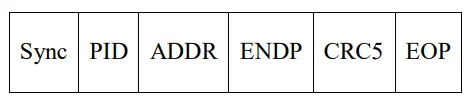
2.1.1 Token Packets
There are three varieties of token packets:
1. “In”: This token packet signals to the USB device that the host has initiated a read transaction.
2. “Out”: The “Out” token packet conveys to the USB device that the host has initiated a write transaction.
3. “Setup”: The “Setup” token is employed to commence a control transfer.
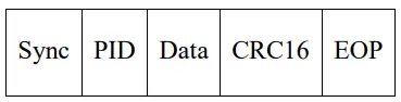
2.1.2 Data Packets
There are 2 types of Data packets. Each data packet is capable of transferring up
to 1024 bytes.
1. Data0
2. Data1
The maximum data payload for the low speed devices is 8 bytes, for full speed
devices is 1023 bytes and for the high speed devices is 1024 bytes.
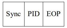
2.1.3 Handshake Packets
There are three distinct handshake packet types, each with a specific purpose. The handshake packet solely includes the PID (Packet Identifier):
1. ACK: This packet signifies the successful reception and acknowledgment of data.
2. NAK: NAK is employed to inform the host that it is unable to send or receive data, often due to interrupt transactions.
3. STALL: The STALL packet serves as a notification to the host that the device necessitates intervention or action on the part of the host.
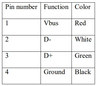
2.2 USB Connector
In the realm of USB connectors, we encounter two distinct types known as Type A and Type B. Each of these USB connectors is equipped with four pins. For a detailed breakdown of the USB connector pin description, please refer to Table 2.2.1.
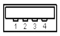
The Type A connector is typically employed for establishing the upstream connection, and it is typically affixed to host devices such as a PC. As depicted in Figure 2.2.1, you can observe the USB Type A connector.
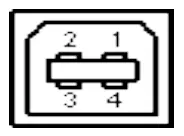
A Type B connector is employed for the downstream connection and is typically found on USB devices like printers and faxes. In this project, a USB Type B connector is utilized.
2.3 USB Transfer Types
The USB specifies 4 different types of transfers.
2.3.1 Control Transfers
Control transfers are employed to establish a USB device, and all enumeration functions occur within these control transfers. Burst transfers initiated by the host characterizes control transfers. The packet size for control transfers varies, with low-speed devices using 8-byte packets, high-speed devices using 8, 16, 32, or 64-byte packets, and full-speed devices employing 64-byte packets.
2.3.2 Interrupt Transfers
Interrupt transfers offer assured latency, unidirectional stream conduit, and error-checking capabilities. These transfers are non-periodic in nature. The device accumulates its interrupt requests until the host actively requests the data. The maximum data payload size for low-speed devices is 8 bytes, while full-speed devices support up to 64 bytes, and high-speed devices can handle a maximum data payload size of 1024 bytes. There exist two distinct categories of interrupt transactions:
1. IN: When the host initiates polling of the device, it dispatches IN tokens to the device.
2. OUT: The host transmits data and follows it with the OUT token.
2.3.3 Isochronous Transfers
Isosynchronous transfers encompass time-critical data like video and audio streams. These transfers happen at regular intervals without interruption. Isosynchronous transfers provide assured bandwidth, limited latency, and error detection. It’s essential to note that low-speed devices do not support this type of transfer; only full and high-speed devices can accommodate it.
2.3.4 Bulk Transfer
Bulk transfers are typically employed for transactions that do not have stringent time requirements, such as tasks like printing or scanning. These transfers do not assure a specific latency, and they offer error detection through a 16-bit CRC (Cyclic Redundancy Check) field on the data.
In the USB protocol, bulk transfers are scheduled after isochronous transfers and interrupt transfers. They are typically initiated when there are no other pending transfers in the USB bus. In the context of this project, bulk transfers were utilized for the efficient transfer of substantial data volumes.
2.3.5 Bus Bandwidth Management
The host is responsible for managing bandwidth on the bus, and this task is performed during enumeration. When an endpoint is configured for isochronous or interrupt transfers, the host activates the bandwidth management function. These types of transfers are referred to as periodic transfers. In the case of a high-speed bus, approximately 90% of the bus time is dedicated to periodic transfers, while the remaining 10% is reserved for control transfers. The remaining time is allotted for bulk transfers. On a full-speed bus, 80% of the time is designated for periodic transfers.
2.4 USB Descriptors
USB descriptors hold significant importance in any USB-compatible device. They serve to provide essential information about the host. This information encompasses details such as the device’s version, the maximum number of USB devices that can be configured on the host, the number of endpoints supported by the host, and the types of endpoints the host can handle. These descriptors adhere to a standardized format. The initial field specifies the descriptor’s length, while the subsequent field defines its descriptor type. It’s important to note that if the length field is smaller than the required length, the host will disregard the descriptor. Conversely, if the descriptor length field exceeds the necessary length, the host will discard the extra bits.
![USB Descriptors [3]](https://pic-microcontroller.com/wp-content/uploads/2023/10/USB-Descriptors.webp)
2.4.1 Device Descriptors
Each USB device is equipped with a single device descriptor field. This descriptor stores crucial information about the USB version it adheres to, its product ID, vendor ID, and the maximum number of configuration devices it can support. The product ID and vendor ID combination is utilized to identify and load the appropriate drivers. For a detailed breakdown of the various device descriptor fields, please refer to Table 2.4.1.1.
![Device Descriptor Fields [3]](https://pic-microcontroller.com/wp-content/uploads/2023/10/Device-Descriptor-Fields.webp)
2.4.2 Configuration Descriptors
The power requirements for the specific configuration are outlined in the configuration descriptor. The configuration descriptor also indicates whether the device is self-powered or bus-powered. In the course of device enumeration, the host system examines the device’s configuration descriptor and determines which configuration to activate. The host can enable only one configuration at a time for each device. Table 2.4.2.1 provides an explanation of the different fields within the configuration descriptor.
![Configuration Descriptor Fields [3]](https://pic-microcontroller.com/wp-content/uploads/2023/10/Configuration-Descriptor-Fields.webp)
2.4.3 Interface Descriptors
The interface descriptors provide information about a specific group of endpoints associated with a particular device function. Unlike the configuration descriptor, where only one configuration descriptor can be active at any given time, a device can have multiple interface descriptors enabled simultaneously. For instance, consider a multifunctional device like a printer that can perform tasks such as printing, scanning, and copying. It can have distinct interface descriptors for each of these functions, and all of them can be active concurrently. Table 2.4.3.1 provides details about the different fields found in interface descriptors.
![Interface Descriptor Fields [3]](https://pic-microcontroller.com/wp-content/uploads/2023/10/Interface-Descriptor-Fields.webp)
2.4.4 Endpoint Descriptors
Each endpoint’s transfer type, direction, polling interval, and maximum packet size are stipulated in the respective endpoint descriptor. The control endpoint, by default, is designated as endpoint zero. Configuration of the endpoint descriptor takes place prior to any host-requested descriptors. The host utilizes the endpoint descriptor details to calculate the bus bandwidth. Table 2.4.4.1 elucidates the various fields found within the endpoint descriptor.
![Endpoint Descriptor Fields [3]](https://pic-microcontroller.com/wp-content/uploads/2023/10/Endpoint-Descriptor-Fields.webp)
2.4.5 String Descriptors
These descriptors furnish user-relevant information. The string descriptor is considered as an elective field, and when left unused, it should be explicitly designated as 0. Table 2.4.5.1 offers an elucidation of the diverse string descriptor fields.
![String Descriptor Fields [3]](https://pic-microcontroller.com/wp-content/uploads/2023/10/String-Descriptor-Fields.webp)
3. HARDWARE OVERVIEW
In this chapter, our attention is directed towards hardware elements like the PIC microcontroller, specifically the PIC18F4550 Microcontroller, as well as the Saronix oscillator. Additionally, we delve into the programming of the PIC 18F4550 by means of the PICKit 2.
3.1 PIC Microcontroller
The abbreviation “PIC” represents “Peripheral Interface Controller.” PICs are a family of microcontrollers created by Microchip Technology, known for their high performance and affordability. These microcontrollers utilize the Harvard architecture. Thanks to their cost-effectiveness, widespread availability, a wealth of application notes, free development tools, and the ability for serial programming, they have become the preferred choice for developers.
PIC microcontroller architectures encompass numerous features, including a compact instruction set, a RISC architecture, an integrated oscillator with selectable speeds, user-friendly in-circuit programming, and debugging capabilities.
3.2 PIC18F4550 Microcontroller
The PIC18F4550 microcontroller offers high performance at a budget-friendly price point. It features an expanded flash memory for program storage and is fully compatible with the USB communication module. This microcontroller supports both low-speed and full-speed USB transactions, accommodating control, interrupt, isochronous, and bulk transfers. It can be connected to up to 16 bidirectional endpoints. The pin diagram for the PIC18F4550 is illustrated in Figure 3.2.1. The chip itself has 40 pins available for connections, and it is a dual in-package configuration with five input/output ports, as depicted in Figure 3.2.1.
![PIC18F4550 [2]](https://pic-microcontroller.com/wp-content/uploads/2023/10/PIC18F4550.webp)
![PIC18F4550 Pin Description [2]](https://pic-microcontroller.com/wp-content/uploads/2023/10/PIC18F4550-Pin-Description.webp)
3.3 Oscillator
The PIC18F4550 device offers twelve distinct oscillator modes for operation. In HS, HSPLL, XT, and XTPLL oscillator modes, a crystal is connected to the OSC1 and OSC2 pins to initiate oscillation. Table 3.3.1 outlines various combinations of capacitors and crystals for design purposes. An internal postscaler is provided to allow users to select a clock frequency different from that of the crystal. The frequency division is determined by the CPUDIV configuration bits, enabling users to opt for a clock frequency that matches the oscillator frequency or is set at 1/2, 1/3, or 1/4 of the oscillator frequency. When the microcontroller operates in HS mode, an external clock can be utilized, leaving the OSC2 pin unconnected. Figure 3.3.1 illustrates the crystal connection with the PIC microcontroller.
![Oscillator Connection to the PIC18F4550 [2]](https://pic-microcontroller.com/wp-content/uploads/2023/10/Oscillator-Connection-to-the-PIC18F4550.webp)
![Various Capacitor and Crystal Combination [2]](https://pic-microcontroller.com/wp-content/uploads/2023/10/Various-Capacitor-and-Crystal-Combination.webp)
3.4 PICKit 2
The PICKit 2 serves as an economical device for programming PIC microcontrollers and is compatible with most of Microchip’s flash microcontrollers. It comes equipped with status LEDs that provide information as follows:
– Power (green): Illuminates when the PICKit 2 microcontroller programmer is receiving power via the USB port.
– Target (yellow): Indicates that the PICKit2 microcontroller programmer is providing power to the target device.
– Busy (red): Lights up when the PICKit 2 microcontroller programmer is engaged in a function.
The push button, although not currently in use, is intended for initiating a function that will be implemented in the near future.
Source: PIC MICROCONTROLLER BASED USB STORAGE
- What is the main objective of the project?
The main objective is to implement the USB protocol and manage reading and writing of packets of various sizes in the PIC microcontroller memory. - Which microcontroller is used in the project?
The project uses the PIC18F4550 microcontroller. - What software was developed for the project?
A Visual C# application with a graphical user interface and debugging capabilities was developed. - Which hardware components connect the design to the computer via USB?
The PIC18F4550, a Saronix 20 MHz oscillator, PICKit 2, and a USB Type B connector connect the design to the computer via USB. - What USB transfer type was used for large data transfers in the project?
Bulk transfers were used for efficient transfer of substantial data volumes. - What packet types are defined in the USB protocol according to the article?
The USB protocol defines token packets (IN, OUT, SETUP), data packets (Data0, Data1), and handshake packets (ACK, NAK, STALL). - How many devices can a USB bus accommodate?
A USB bus can accommodate up to 127 devices. - What clock frequencies are required for USB operation on the PIC18F4550?
The PIC18F4550 requires a clock frequency of either 6 MHz or 48 MHz depending on low-speed or full-speed USB mode. - What are the roles of device, configuration, interface, and endpoint descriptors?
Device descriptors identify device version and IDs; configuration descriptors state power requirements and selectable configurations; interface descriptors describe groups of endpoints for functions; endpoint descriptors specify transfer type, direction, polling interval, and max packet size. - What test cases were incorporated in the project?
Test cases include writing a single packet, reading and writing a single packet, writing one then reading 128 packets, writing 128 then reading one, and writing a single packet with a read timeout.