Summary of Building Blocks for Success: A Structured Framework for Microchip PIC Microcontroller Applications
This paper presents the MPIC development system (MPICds), a modular hardware and software framework for rapid prototyping with Microchip PIC microcontrollers, emphasizing easy fabrication, ICSP programming via free PC tools, and support for high-level, model-based development (block diagrams/flowcharts). Designed for education, MPICds includes a main board, programmer, and plug-in modules, and promotes safe, flexible use across secondary and university curricula to bridge simulation, prototyping, and on-target testing.
Parts used in the MPIC development system (MPICds):
- Main board with Textool socket and 10-pin IDC connectors
- Power supply with Graetz bridge (full-wave bridge)
- Resistor chains for pull-up/pull-down on microcontroller ports
- Jumpers/short-circuit connectors for configuration
- RC and quartz crystal oscillator footprints
- Reset circuit with push-button
- Programmer (compatible with JDM and P16PRO modes)
- 74HCT367 high-speed CMOS buffer IC (in programmer)
- Transistors and Zener diodes (voltage adaptation in programmer)
- 100 mA current-limit power for programmer
- Microchip-compliant FCC connector (on programmer PCB)
- 10-pin IDC cable for programmer-main board connection
- Plug-in modules, e.g., PortKEY (input key)
- PortLED module (LED output indicator)
- LCDa16 module (2x16 alphanumeric LCD)
- DS1820 temperature sensor module
- PDIP-package PIC/dsPIC microcontrollers (ICSP-capable)
- Single-sided printed circuit boards (PCBs)
Abstract
This paper introduces a framework designed for creating applications centered around a Microchip PIC microcontroller (μC). Comprising both hardware and software tools, this framework facilitates the development and transfer of program code from a personal computer to the microcontroller, as well as the evaluation of its performance on rapid prototyping hardware. The initial section of the paper delves into hardware design, emphasizing a modular approach that allows for customization tailored to each application, ensuring optimal adaptability. Known as the MPIC development system (MPICds), it includes a programmer, a main board with adapters catering to various chip packages, and plug-in modules. All these hardware components are engineered for easy fabrication by any potential user.
Programming the selected microcontroller is achieved via the standard ICSP mode using freely available PC programs, detailed in the subsequent section of the paper covering the software aspect of the framework. Alongside programming tools, the software discussion encompasses code development tools, with a particular emphasis on employing high-level tools where algorithms are represented through various graphical notations such as block diagrams, as opposed to traditional C or assembly code. Throughout the paper, special attention is dedicated to illustrating the framework’s utility in electrical engineering education. Apart from offering recommendations for implementation across different educational levels, the focus lies on embracing contemporary design methodologies and ensuring robust hardware design. The deliberate construction of the hardware is engineered to withstand incorrect usage without compromising any of its components.
1. INTRODUCTION
In our modern daily routines, an array of devices, such as phones, household appliances, and automobiles, are equipped with sophisticated “smart” electronics, often embedded within. At the core of these embedded systems lies a microcomputer specifically tailored to control particular applications—a microcontroller (μC) or digital signal processing (DSP) device. These microcomputers, integrated onto a single chip, encompass not only a central processing unit and memory but also various application-specific peripherals like AD and DA converters, timers, and communication modules [1]. As the most widely produced processing units, microcontrollers assume a crucial role in electronic control systems, captivating interest not only in electrical engineering but also across mechanical and industrial sectors.
As components grow increasingly intricate, a methodical design approach and the ease of testing and verifying the developed system on actual hardware become paramount. Prototyping applications, whether in hardware or software, thus hold significant importance in the design phase. Given that microcontroller-based application design entails a blend of computer programming and digital circuitry construction [2], proficiency in both domains is essential. Moreover, as technology progresses rapidly, educational methodologies in this realm must evolve accordingly [3,4]. Educational institutions, tasked with imparting requisite skills and knowledge to students, must stay attuned to industry needs and practices.
Conversely, the industry bears the responsibility of articulating its specific requirements and nuances, fostering a symbiotic relationship with educational institutions to ensure alignment between educational offerings and industry demands.
Recognizing the need to adapt to evolving design paradigms in contemporary systems, innovative pedagogical approaches supported by appropriate hardware and software tools are imperative [1]. With this objective in mind, we have developed a framework designed to streamline and expedite this process. The hardware component of this framework is the MPIC development system (MPICds), characterized by its modular structure [7]. This modularity allows for customization tailored to each specific application. The primary hardware components include the main board housing the microcontroller and the programmer utilized for firmware download from a personal computer (PC) to the microcontroller. Complementing these major hardware elements are various plug-in test modules designed for program verification purposes.
As for the software tools within the framework, they can be categorized into those facilitating program code development and those enabling microcontroller programming. In the latter category, we exclusively considered freely available programs, whereas for development tools, our focus lies on those offering high-level design capabilities, wherein algorithms are depicted through various graphical representations (e.g., block diagrams, flowcharts) rather than being scripted in C or assembly code.
The remainder of this paper unfolds as follows: Section 2 offers a brief introduction to the general embedded system design cycle. Section 3 elaborates on the key features of the framework’s hardware components, specifically the MPIC development system. Subsequently, Section 4 delves into the software components. Section 5 explores the framework’s suitability for educational purposes. Finally, Section 6 concludes the paper by outlining ideas and plans for further development of the framework.
2. EMBEDDED SYSTEM DESIGN CYCLE
Due to the increasingly intricate nature of embedded systems in recent decades, developers are encountering greater challenges in maintaining the competitiveness of their products in the market [8]. In this scenario, adopting systematic design approaches becomes imperative to integrate technical, cost, and time-to-market feasibility factors rather than compromising on any aspect [5, 9]. The design cycle is typically depicted using a V-diagram representation, particularly in the context of embedded systems design [5]. As shown in Figure 1, the diagram illustrates the progression of design steps over time, with the horizontal axis representing time. However, since the design process often involves iterations, development cycles between the left and right legs of the diagram rather than following a strictly linear path through the steps [10]. On the other hand, the vertical axis signifies the level of abstraction of system components, with higher-level views represented at the top steps and more detailed processes depicted at the bottom steps.
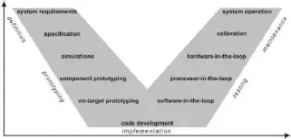
The V-diagram depicted in Figure 1 illustrates the flow of an embedded system design process. It commences with the specification of system requirements, followed by their processing. The system, located along the left leg of the V-diagram, undergoes decomposition into smaller components. At the bottom of the V-diagram lies the implementation stage, marking the transition from decomposition to re-composition as it ascends along the right leg. Here, the system’s entities are recombined into larger components, ultimately resulting in the assembly of the final system.
The primary objective of each design process is to achieve a system that operates in accordance with the specifications, while aiming to narrow the V-diagram as much as possible. This narrowing facilitates efficiency gains, reducing both time and cost associated with design [10]. The framework outlined in this paper contributes to narrowing the embedded system design V-diagram by offering a standardized set of tools utilized across prototyping, implementation, and testing stages.
During the prototyping stage, a simulation model is initially developed to match the requirements. Subsequently, design components are prototyped on general hardware to validate feasibility. Timing characteristics are not modeled in this phase, and may vary in the actual design. Upon successful validation of component behavior, on-target prototyping is conducted using the intended processing device, such as a microcontroller in our case. This step validates characteristics like code compilation, fixed-point precision effects, and interactions among system components.
Upon confirming correct operation through simulations and prototyping, highly optimized code is generated in the implementation stage. Finally, during the testing stage, the design is evaluated as it progresses along the right leg of the V-diagram. Various configurations, such as software-in-the-loop, processor-in-the-loop, and hardware-in-the-loop, are employed in these steps [8].
3. MPIC DEVELOPMENT SYSTEM
The objective of the MPICds [7] is not to rival commercially available platforms, but rather to efficiently integrate freely accessible tools and readily available components. Similarly, serving as an educational aid akin to E-blocks [11] or MILES [12], the system is not tailored to any specific curriculum but can be easily adapted to secondary school or university courses. Its modular design makes it particularly suitable for self-directed learning, allowing users to construct components as needed, thereby reducing overall system costs.
In the subsequent subsections, detailed descriptions are provided regarding the assumptions considered during the design of the MPICds and its essential hardware components.
3.1 Design assumptions
Considering the educational focus of the MPICds, the choice of Microchip’s PIC and dsPIC microcontroller families [13] was deliberate, selected over other options from various manufacturers for several reasons [1,14]. Firstly, these microcontrollers are widely accessible in the market at relatively affordable prices. Additionally, there is a plethora of quality development and programming support tools available, some even freely accessible, facilitating firmware transfer using a standardized interface. Moreover, their popularity in hobby electronics adds to their suitability for educational purposes.
Several assumptions and limitations guided the design of the MPIC development system:
– The software development process for applications typically involves a cyclic process of coding, testing, and downloading to a microcontroller, necessitating support for these functionalities.
– Modular structuring of the system ensures maximum flexibility and facilitates rapid prototyping.
– The design avoids the use of pre-programmed chips.
– Basic accompanying software tools should be freely available online.
– Microcontroller selection is limited to those compatible with In-Circuit Serial Programming (ICSP) modules, a feature present in the majority of PIC microcontrollers.
– Microcontrollers are further restricted to those available in PDIP package types.
– The programmer must allow firmware download from a PC to the microcontroller via parallel (LPT) or serial (COM) ports.
– The programmer should be designed for permanent connection to the main board during programming or application execution.
– All microcontroller I/O pins must be accessible via plug-in module connectors on the main board.
– Printed circuit boards (PCBs) should be single-sided to facilitate easy fabrication by users.
– Microcontroller operation settings using external signals should be accessible through jumpers or short-circuit connections.
– Plug-in modules should be designed to prevent damage to system components even in cases of incorrect usage.
These assumptions address common problems and difficulties encountered by beginners in the realm of microcontrollers. While the resulting system may not be the most optimized variant, it provides an effective means for individuals to familiarize themselves with the entire design cycle.
3.2 Main board
Instead of a 40-pin microcontroller, these components are linked to the Textool socket. The primary board incorporates a power supply featuring a Greatz bridge, serving a dual purpose. Firstly, it functions as a traditional full-wave bridge, accommodating input voltage from either AC or DC sources. Secondly, it serves to safeguard the connected power supply in the event that the programmer possesses its own power source. Both plug-in modules and the programmer connect to the main board via 10-pin IDC connectors.
Each IDC connector on the main board provides access to one microcontroller port along with the supply voltage for connecting plug-in modules. Additionally, on the PORTE IDC connector, the microcontroller’s pins for external reset circuits, external oscillators, and external AD converter supply voltage are accessible. Each microcontroller port is linked to a resistor chain capable of performing pull-up or pull-down functions, with operation set via appropriate jumper connections.
The IDC connector for the programmer attachment offers all necessary pins for connecting ICSP-compatible programmers. Moreover, the remaining pins on this connector provide access to the microcontroller’s USART module pins, usable for firmware downloading via bootloaders. Manual control over the programmer’s virtual connection-disconnection to the microcontroller is facilitated by a single switch.
Designated spots for RC and quartz crystal oscillators are included on the printed circuit board. Additionally, a straightforward reset circuit featuring a key as an execution unit is integrated to ensure it doesn’t disrupt the activity of the ICSP programmer.
3.3 Programmer
When designing the hardware component of the programmer, three key design assumptions were carefully considered. Firstly, it was imperative that the microcontrollers are programmable in ICSP mode. Secondly, firmware download needed to be achievable using either a serial or parallel PC port. Lastly, it was essential that the accompanying software programming tools are freely accessible online.
Consequently, the programmer was engineered to be compatible with both the JDM [16] and P16PRO [17] programmers. The JDM programmer utilizes the COM port for firmware download, while the P16PRO programmer employs the LPT port. ICSP, a synchronous programming procedure specified by Microchip for programming PIC microcontrollers [18], utilizes five or six microcontroller pins for reading and writing firmware. The inclusion of the sixth pin is necessary for microcontrollers compatible with Low-Voltage ICSP, enabling a second type of programming procedure.
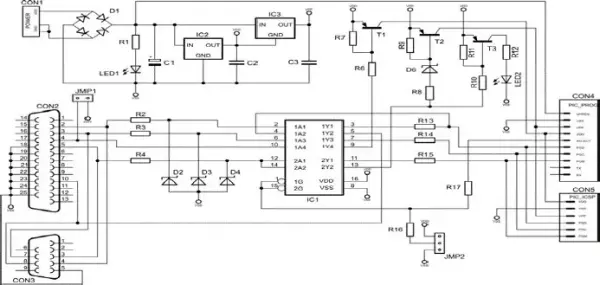
The electrical scheme of the programmer, illustrated in Figure 3, comprises standard elements and can be connected to the main board using an IDC connector cable. Similar to the main board, the programmer features its own power supply for two additional purposes. Firstly, to safeguard the microcontroller against damages during programming via a built-in 100 mA current limit, and secondly, to enable autonomous use, such as programming microcontrollers already integrated into end applications. For such scenarios, a Microchip-compliant FCC connector is provided on the printed circuit board.
The primary component of the programmer, bridging the PC and microcontroller, is the high-speed CMOS integrated circuit 74HCT367. It contains six three-state non-inverting buffers driven by two enable inputs, facilitating the transmission of firmware between the PC and microcontroller. The circuit also incorporates additional elements, including transistors and Zener diodes, which are crucial for adapting COM port voltage levels, as they are not TTL compatible unlike LPT ports. Transistors serve to ensure appropriate current loads or to convert voltage levels, particularly necessary for generating voltages higher than 5 V in ICSP programming mode.
3.4 Plug-in modules
To facilitate testing and validating programs programmed into microcontrollers, a series of fundamental test circuits has been devised. These circuits, referred to as plug-in modules, are connected to the main board for each application design. Some of these modules include:
– PortKEY: A module designed to manipulate the state of a specific microcontroller’s input using a key.
– PortLED: A module utilized to indicate the output of a particular microcontroller by illuminating an LED.
– LCDa16: An LCD module featuring two 16-character alphanumeric lines.
– DS1820: A module equipped with a Dallas DS1820 temperature sensor.
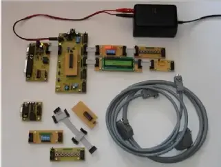
To maximize versatility in usage, these modules are constructed in a manner that allows their final function to be tailored by configuring jumpers or short-circuit connections. An example of the fabricated development system is depicted in Figure 4. Further details regarding each component of the system can be found in [7], including the electrical schematics and proposed printed circuit board design.
4. SOFTWARE TOOLS
Throughout the development of microcontroller-based applications, a variety of software tools are employed. When working with the PIC microcontroller family, there exists a plethora of high-quality software tools offered by various manufacturers. Many of these tools, including some provided by Microchip, are freely accessible online with their full functionality. Broadly speaking, these tools can be categorized into development tools, which process the source code, and programming tools, which facilitate the transfer of compiled firmware from a PC to the microcontroller.
4.1 Development tools
Microchip provides a comprehensive suite of development tools tailored for its PIC microcontroller family. This suite encompasses an integrated development environment (IDE), commonly referred to as MPLAB [19], comprising assembler, C compiler, simulator, product selector guide, and more. Alongside these tools are programming utilities, typically designed to interface exclusively with Microchip’s proprietary hardware. Consequently, the following subsection introduces alternative software tools intended for use with our MPICds programmer.
In addition to Microchip’s development tools, developers have the option to select from a variety of tools offered by other manufacturers. These tools typically include compilers for higher-level languages such as C, Basic, and Pascal, as well as real-time operating systems and tools tailored for operating systems other than Microsoft Windows, such as Linux. Notable examples of higher-level language compilers include the HI-TECH PICC, IAR Embedded Workbench, CCS C, and mikroC C language compilers. These compilers come equipped with extensive sets of common and microcontroller-specific libraries, enabling their integration with either their own integrated development environments or Microchip’s MPLAB IDE.
While mikroC is primarily used for developing code for 8-bit microcontrollers, such as the PIC10, PIC12, PIC14, PIC16, and PIC18 families, HI-TECH, IAR, and CCS C tools also cover 16-bit microcontrollers, including the dsPIC and PIC24 families. Traditional code development tools, like those mentioned above, typically occur later in the design cycle, during the implementation and testing stages, potentially leading to errors due to the late integration of hardware and software.
To address this issue, real-time prototyping hardware, such as the MPICds for PIC microcontrollers, allows for earlier implementation aspects to be addressed in the design cycle, complementing traditional prototyping approaches with real testing. Model-based design tools have also emerged as valuable resources, facilitating the development of simulation models in early design stages and verifying them on real hardware through automatic code generation. One commonly used model-based design tool is The MathWorks’ Simulink platform, which provides an interactive graphical environment for developing algorithms in block diagrams. Simulink models can be integrated into Microchip’s MPLAB IDE projects via a plug-in for MATLAB and Simulink, allowing for the inclusion of automatically generated code into 16-bit microcontroller applications.
Another tool, the Embedded Target for 16 bits PIC, extends the functionalities of Simulink by providing blocks for microcontroller-specific peripherals, enabling the compilation and building of models for 16-bit microcontrollers directly from Simulink without requiring MPLAB IDE. In the realm of open-source tools, Evidence’s Scilab/Scicos Code Generator for FLEX has emerged as a model-based design platform. Similarly, to Octave, Scilab is an open-source platform for numerical computation, while Scicos serves as its block diagram modeler and simulator. Block diagrams developed in Scicos can be exported to ERIKA Enterprise and run on the FLEX board for dsPIC microcontrollers.
Lastly, Flowcode from Matrix Multimedia supports simulation and code transfer to a subset of 8-bit microcontrollers, with code generated from flowchart-type block diagrams. These model-based design tools, though still in early development stages, aim to cover the entire design cycle and represent significant advancements in facilitating efficient and error-free microcontroller programming and development.
4.2 Programming tools
The hardware component of the MPIC development system can be complemented with one of the following freely available software programming tools:
– IC-Prog [29]: This tool facilitates microcontroller programming via the PC’s COM port when the programmer is set to JDM compatible mode.
– PICALL [17]: Designed for programming through the PC’s LPT port, compatible with the programmer set to P16PRO mode.
– WinPic [30]: A fully customizable programmer capable of programming the microcontroller using either the serial or parallel port.
Specific settings for optimal program operation with the provided programmer hardware can be accessed in [7].
5. FRAMEWORK AS AN EDUCATIONAL TOOL
Given that all predefined assumptions of the MPICds framework have been met during the design process, along with the selection of efficient supporting software tools, the development system has evolved into a robust apparatus suitable for educational purposes in secondary schools and university courses. Notably, its utility extends beyond electrical engineering education; its modular hardware and user-friendly software tools allow for quick adaptation to various engineering branches without necessitating extensive programming skills. Additionally, the framework is proficient enough to cater to experts in designing applications based on microcontrollers.
Engineering education relies heavily on models for problem-solving, utilizing graphical representations to illustrate the behavior of objects under study. In the context of microcontroller application design, where proficiency in both digital circuit construction and programming is paramount, circuit schematics depict hardware configurations, while block diagrams elucidate software execution flows. Similar challenges arise in product design cycles and educational processes, both requiring efficient development tools to overcome them. Our framework facilitates the educational process by enabling students to construct hardware models by interfacing microcontrollers with MPICds plug-in modules, seamlessly transitioning from high-level models to efficient product implementations using modern software tools.
When utilized in secondary school courses, the framework serves as versatile educational equipment across multiple subjects. It can be employed in courses covering the fundamentals of microprocessors and microcontrollers, programming (in assembler, higher-level languages, or through automatically generated model code), and further in courses concerning the design of additional plug-in modules. Motivated students may even undertake the fabrication of the system or its components independently.
At the university level, the framework finds utility in courses focusing on microprocessors, microcontrollers, or embedded systems, providing support for both programming and hardware peripheral design. Given the increasing demand for interdisciplinary education, the system appeals to students in other engineering disciplines such as computer, mechanical, chemical, or industrial engineering. Subjects that the system can assist in covering include computer architectures, digital signal processing, mechatronics, automated measuring, and more.
- What is the MPIC development system used for?
It is a modular hardware and software framework for developing and prototyping applications centered on Microchip PIC microcontrollers. - How are microcontrollers programmed in the MPICds?
Microcontrollers are programmed via standard ICSP mode using freely available PC programs and the provided programmer hardware. - Can the MPICds be fabricated by users?
Yes, all hardware components are engineered for easy fabrication by potential users, using single-sided PCBs and common components. - Does the MPICds support high-level model-based development?
Yes, the framework supports high-level tools that represent algorithms with graphical notations like block diagrams and flowcharts. - What kinds of plug-in modules are available?
Examples include PortKEY for input keys, PortLED for LED outputs, LCDa16 for 2x16 LCDs, and DS1820 temperature sensor modules. - Which programmers are compatible with the MPICds hardware?
The programmer is compatible with JDM (serial COM port) and P16PRO (parallel LPT port) modes, and works with IC-Pro, PICALL, or WinPic software. - Is the MPICds suitable for educational use?
Yes, it is designed for secondary and university courses, supporting programming, hardware peripheral design, and interdisciplinary education. - Are all microcontroller I/O pins accessible?
Yes, all microcontroller I/O pins are accessible via plug-in module IDC connectors on the main board. - How does the system protect components from incorrect use?
The hardware is deliberately constructed with protections such as current-limited programmer power, resistor chains, and module designs to prevent damage under incorrect usage.