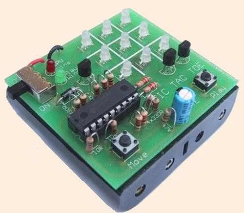
This project is not to introduce Tic Tac Toe. Everyone knows this game.
It’s to introduce two features. Bi-coloured LEDs, microcontrollers and the skill of writing an ALGORITHM.
You can use the project to learn the skills of creating the Tic Tac Toe program or create animations on the 3×3 display.
Tic Tac Toe is one of the simplest yet most-challenging games to be invented. With just a choice of nine locations, two players can pit their wits and very quickly work out who is superior.
Even though the game is very simple, it has an enormous fascination. It is possible to produce a program capable of playing the game and have a high degree of “computer win.”
Although the program we have produced does not use high-level strategy, it plays an interesting game.
The program has been kept as simple as possible to show how to produce routines that carry out a function.
One of the sub-routines, PWin, has been written in a linear-mode to show how long, but simple, it is. An almost identical sub-routine is CWin. It has been written using loops and this requires extra files to keep track of the “looping feature.”
Many of the sub-routines are ALGORITHMS. This is a routine that solves a problem. The routine looks to see if a certain condition is present and produces an answer. This is the basis of “Computer Intelligence” or “Artificial Intelligence.” (AI). When a number of these routines are combined and a result is obtained in a very short period of time, the computer appears to be “clever.”
There is nothing more rewarding than producing a program that delivers “feedback” of this type. It’s the programmers’ high-light of the day.
The microcontroller we have chosen is a PIC16F628. (It’s an upgrade of the PIC16F84A and with a couple of components added to the board, an ‘F84 could be used.)
This is one of the latest low-cost micro’s on the market and is an ideal starting-point for beginners to the “art of programming.”
The micro is easy to use and has a re-programmable feature that allows it to be programmed almost any number of times.
A game or toy is an ideal place to start as you know how it is played or how it is used and it’s just a matter of seeing how the routines are created – so you can copy them or use them in other programs.
There is one other advantage of using a game. It introduces strategy. If the game is played against the “computer” and the computer has a chance of winning, it appears to have “intelligence.”
The program for this game can be developed in two different ways -as an ALGORITHM or in “linear-mode.” An algorithm is essentially a routine consisting of instructions that come up with a definite answer. The program could consist of a single, extremely complex algorithmical sub-routine. It would take hours to explain the thinking behind the structure of the routine and beginners would be left, floundering. The solution is to produce a program with very simple sub-routines. And this is what we have done.
A linear-mode layout makes the micro run through the program and find a set of instructions that applies to the particular condition. This type of layout requires more instructions but it is much easier to follow.
Many of the programs on the web (and in books), have been developed by very clever programmers and it may take an hour or more to work out what the program is doing!
This is not the approach we are taking. The routines we have produced are very simple and each instruction is fully explained.
Don’t be dissuaded by the length of the program. It’s really individual sub-routines that can understood if you sit down and “apply yourself.”
ATTRACT MODE
When the project is turned on, the screen flashes and shows the effectiveness and capability of the bi-coloured LEDs. This is called the ATTRACT MODE and is sometimes used in amusement machines to attract players. The LEDs flash from red to orange to green and then a single LED in the centre of the display gradually changes from red to green. There are 256 steps in the change. To produce this gradual effect, takes about 20 instructions and the program shows how this is done.
The routines for the ATTRACT MODE are separate from the Tic Tac Toe game and the buttons are monitored during the Attract Mode to allow the player to go to the game. When either button is pressed, the micro goes to Tic Tac Toe.
THE FIRST STEP
The first step is to work out how the micro will drive the display. Although the display consists of 9 LEDs, each LED contains two elements – a red and green emitter.
The output is orange when both emitting chips are driven and when either chip is driven, the output is red or green.
Other LEDs are also available with three chips inside to produce red, green and blue. When all chips are driven, the output is white light.
Bi-coloured LEDs have 3 leads. The two light-emitting parts of the LED have the cathodes connected together and this is taken to the 0v rail. In our project, we have connected the LED so that the lead to the red chip is on the left and the green is on the right.
This means the display is very similar to driving 18 separate LEDs.
This allows a scanning routine with a “run-of-three.”
For more detail: TIC TAC TOE game using PIC16F628

