Summary of PIC Stepper Motor Controller using PIC16F84A with Proteus Simulation
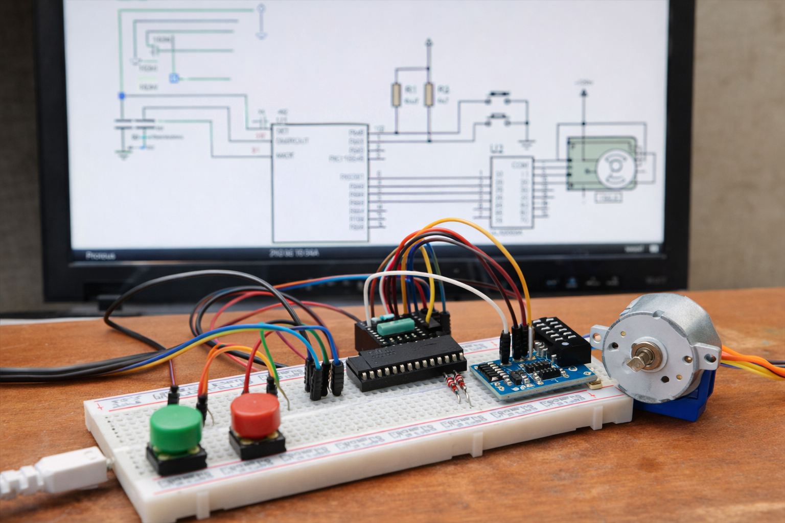
This project uses a PIC16F84A microcontroller and ULN2003A driver to control a stepper motor bidirectionally via two push buttons (RA0 clockwise, RA1 counter-clockwise). The PIC generates four-bit stepping patterns on RB0–RB3, with a software delay controlling speed. Implemented and tested in Proteus, the design demonstrates bit-rotation step sequencing, driver interfacing for higher currents, and is suitable for learning embedded motor-control fundamentals without physical hardware.
Parts used in the PIC Stepper Motor Controller using PIC16F84A with Proteus Simulation:
- PIC16F84A Microcontroller
- ULN2003A Darlington Driver IC
- Stepper Motor
- Push Buttons (2)
- Crystal Oscillator (1 MHz)
- Capacitors (1 nF ×2)
- Resistors (4.7kΩ ×2)
- Power Supply (+12V for motor)
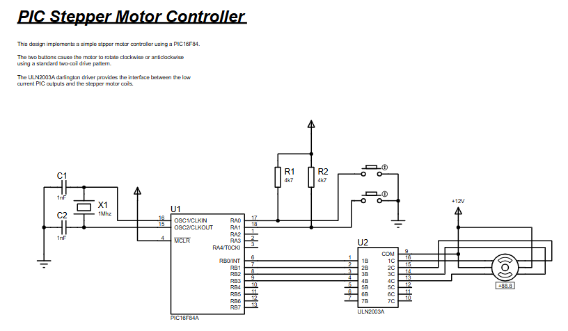
- How does the project control motor direction?
Two push buttons on RA0 and RA1 select clockwise and counter-clockwise; the PIC shifts the output pattern left or right accordingly. - What microcontroller is used?
The project uses a PIC16F84A microcontroller. - How are the motor coils driven safely?
The ULN2003A Darlington driver amplifies current from PORTB before driving the stepper motor coils. - Which pins produce the stepping sequence?
PORTB pins RB0–RB3 output the stepping pattern. - How is motor speed adjusted?
Speed is controlled by a delay routine in software that sets the stepping interval. - Can this project be tested without physical hardware?
Yes, it is implemented and tested using Proteus simulation. - What language is the firmware written in?
The firmware is written in PIC assembly language using MPASM. - What does the pos variable do in the code?
pos stores the current stepping pattern representing the energized motor coil. - Which button rotates the motor clockwise?
Button on RA0 rotates the motor clockwise. - Which button rotates the motor counter-clockwise?
Button on RA1 rotates the motor counter-clockwise.