Summary of Digital Clock using PIC Microcontroller Interrupt – XC8
A PIC microcontroller Timer1, clocked by a 32.768 kHz watch crystal, is used as a low-cost real-time clock (RTC) replacing external RTC ICs. Timer1 (16-bit) overflows generate interrupts to maintain seconds; time/date are set/read via serial (MAX232) to a PC and shown on a 16x2 LCD. MPLAB XC8 peripheral library provides Open_RTCC and update_RTCC routines to configure Timer1 for 1 Hz interrupts and handle TMR1 flags. An LED blinks each second to indicate the clock is running.
Parts used in the Digital Clock:
- PIC microcontroller with Timer1 (example: PIC18 series)
- 32.768 kHz watch crystal
- Two 33 pF capacitors
- MAX232 IC
- 16 x 2 LCD display
- LED (D1)
- 10K resistor (optional for MCLR pull-up)
- Connections/wiring and power supply
A Real Time clock (Digital Clock) can be made easily by using Timer 1 of a PIC Microcontroller.
The Timer1 module exists in most of the series of PIC, this module can be used to easily implement a real-time clock. Instead of an external real-time clock device like a DS1307, an inexpensive 32.768 kHz watch crystal and two 33 pF capacitors are used to complete the circuit.
In this application, Timer1 is clocked by an external crystal (32.768 kHz) connected across RC0 (T1OSO) and RC1 (T1OSI).
 Timer TMR1 module is a 16-bit timer/counter, which means that it consists of two registers (TMR1L and TMR1H).
It can count up 65.535 pulses in a single cycle before the counting starts from zero.
These registers can be read or written to at any moment.
In case an overflow occurs, an interrupt is generated if enabled.
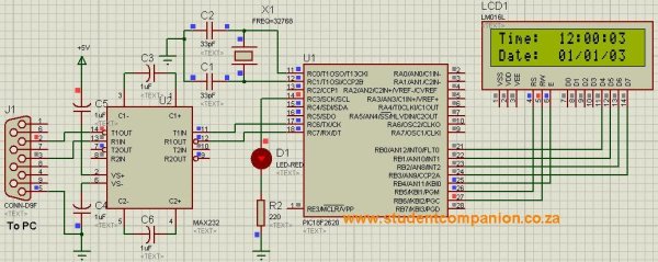
Circuit Diagram
As shown on the circuit diagram above on figure 1, an external 32.768 kHz watch crystal and two 33 pF capacitors are connected to Timer1 on PORTC, RC0 (T1OSO) and RC1 (T1OSI).
The PIC uses an internal oscillator and the MCLR is disabled. If an external oscillator is needed, it can be connected to pins 9 (OSC1) and 10 (OSC2) and if the MCLR is needed to reset the PIC, it can be connected to positive supply via a 10K resisitor.
Time and Date are read from a Personal Computer (PC) via a serial connection. A MAX232 IC is used to convert the voltage logics from the PIC to RS232 standard and vice versa. To learn more on serial connection, please refer to the article: PIC Microcontroller Communication: The RS232.
When power is switched on, a message will be sent to the PC to set the date and the time.
A 16 x 2 lines LCD display is connected to PORT B. refer to the Interfacing LCD Display with PIC microcontroller article to learn more.
LED D1 flashes each second as the clock is running.
 Code
Code
MPLAB XC8 compiler is used to write the code.
The PIC18 Peripheral Library found inside the installation folder of CX8 compiler contains a full description of Real-Time Clock and Calendar (RTCC) function simulated using Timer1.
Open_RTCC(): Configures Timer1 to work as clock source for RTCC, enables Timer1 interrupts, and writes a value into TMR1H & TMR1L registers to get 1second interrupt.
update_RTCC(): checks for the TMR1 interrupt flag, refreshes TMR1H if interrupt has occurred and returns the state of TMR1IF
For more detail: Digital Clock using PIC Microcontroller Interrupt – XC8
- How is the real-time clock implemented in this project?
Using Timer1 of the PIC microcontroller clocked by an external 32.768 kHz watch crystal to generate 1 Hz interrupts that maintain time. - What external components replace a DS1307 in this design?
A 32.768 kHz watch crystal and two 33 pF capacitors are used instead of a DS1307. - How is time and date communicated with a PC?
Via a serial connection using a MAX232 IC to convert between PIC logic levels and RS232 standard. - Which PIC pins are used for the Timer1 crystal connection?
RC0 (T1OSO) and RC1 (T1OSI) are used for the external 32.768 kHz crystal connection. - What indicates the clock is running?
LED D1 flashes each second as the clock runs. - Where is the time displayed?
On a 16 x 2 LCD display connected to PORTB. - Which compiler and library functions are referenced for this project?
MPLAB XC8 compiler and the PIC18 peripheral library functions Open_RTCC and update_RTCC are used. - What does Open_RTCC do?
Open_RTCC configures Timer1 as the RTCC clock source, enables Timer1 interrupts, and writes values into TMR1H and TMR1L to get a 1 second interrupt. - What does update_RTCC check?
update_RTCC checks the TMR1 interrupt flag, refreshes TMR1H if an interrupt occurred, and returns the state of TMR1IF.