Summary of 30 volts Panel Volt Meter Using PIC MCU
This project uses a PIC16F676 microcontroller with its internal 10-bit ADC and a resistor-divider to measure up to 30 V DC, displaying the voltage on three multiplexed common-anode 7-segment LEDs. A 47k resistor and 10k trimpot form the divider (scale 30 V to 5 V), a 0.1 µF capacitor stabilizes the ADC input, and a 5.1 V zener provides overvoltage protection. Calibration is done by adjusting the trimpot with a known reference (e.g., 5 V or 12 V). Refresh rate of the multiplexed display is about 50 Hz.
Parts used in the 30 volts Panel Volt Meter Using PIC MCU:
- PIC16F676 microcontroller
- 3-digit common-anode 7-segment displays
- 47k resistor
- 10k trimpot (trim potentiometer)
- Resistor network for voltage divider (47k and 10k trimpot)
- 0.1 µF capacitor
- 5.1 V zener diode
- Current-limiting resistors for 7-segment LEDs (implied in display driving)
- Power supply (5 V VCC)
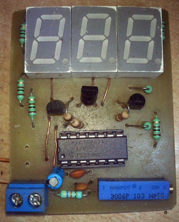
- Wiring, PCB or protoboard
This is a simple application of internal 10-bit ADC(analog to digital converter) of PIC16F676 microcontroller.you can use this circuit to measure up to 30 v dc. the possible applications are on bench top power supply or as a panel meter in various system.
as you can seen in the schematic the 47k resistor and 10 k trim pot is connected ias a voltage divider configuration .we all know very well that by default pic micro controller ADC reference voltage is set to vcc(+5v in this case) . so what we have to do is make such voltage divider that can divide out maximum range 30 volts to 5 volts . so we need is Vin/6 ==> 30/6 =5v voltage divider . and to keep as less as possible attenuation on the under test voltage we have to keep the voltage divider resistor value in few thousand ohms because it takes very little current from the target but as much to drive adc of pic.
calculation
10bit adc resolution we get 1023 maximum count
with 5 v reference we get 5/1023 = 0.0048878 V/Count
means if the adc count is 188 then input voltage is 188 * 0.0048878 == 0.918 volts
but now with the voltage divider the maximum voltage is 30v so the calculations
will be 30/1023= 0.02932 volts/count
if now we get 188 then 188*0.02932==5.5 Volts
you can also increase or decrease the range by changing resistor network and the calculations a little bit.
the capacitor 0.1uf makes the adc input a bit stable because 10bit adc is really sensitive .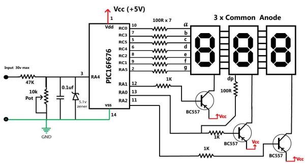
the 5.1v zener will provide over votage protection to the internal adc because it wont allow voltage more than 5.1v.
Accuracy and calibration
overall accuracy of this circuit is great but it totally depends on the values of 47K resistor and 10k trim pot . as fine as you can go by adjustment of the trim pot your accuracy goes fine.
calibration of this circuit is done by adjustment of the 10k trimpot around value of 7.5k or so .
all you have to do is take any standard power like 5v or 12v and apply that to the input of the resistor network and adjust the trimpot until you get correct value on the display
- What microcontroller is used in this project?
PIC16F676 microcontroller is used as the heart and brain of the circuit. - How is up to 30 V measured with a 5 V ADC reference?
A resistor voltage divider (47k and 10k trimpot) scales 30 V down to 5 V for the ADC. - Does the circuit include overvoltage protection?
Yes, a 5.1 V zener diode provides overvoltage protection to the ADC input. - How is the measured voltage displayed?
The converted voltage is shown on three multiplexed common-anode 7-segment displays at about 50 Hz refresh rate. - What stabilizes the ADC input?
A 0.1 µF capacitor is used to make the ADC input more stable. - How is the circuit calibrated for accuracy?
Calibration is done by adjusting the 10k trimpot using a known reference voltage such as 5 V or 12 V until the display reads correctly. - What is the ADC resolution and voltage per count?
The PIC internal ADC is 10-bit (1023 max count); with 30 V full scale this gives about 0.02932 V per count. - Can the measurement range be changed?
Yes, you can increase or decrease the range by changing the resistor network and updating calculations accordingly.