Summary of Microcontroller based Diode and Bipolar Junction Transistor (BJT) tester
This project demonstrates a simple diode and Bipolar Junction Transistor (BJT) tester using a PIC16F688 microcontroller. It leverages the principle that PN junctions conduct current in only one direction to identify normal, open, or shorted components. The device tests transistor types (NPN/PNP) by analyzing conduction across Base-Emitter and Base-Collector junctions through specific I/O pin sequences.
Parts used in Microcontroller based Diode and Bipolar Junction Transistor (BJT) tester:
- PIC16F688 microcontroller
- Push button switches (Select and Detail)
- 1 K resistors
- RA0, RA1, and RA2 port pins
- D1 and D2 input labels for diode testing
- E, B, and C test leads for transistors
Introduction
Most of the digital multimeters these days have built-in features for testing diodes and sometimes transistors. The purpose of this project is to demonstrate a simple way to construct a testing device for diodes and bipolar junction transitors (BJTs) using a microcontroller. The testing algorithm is based on a simple fact that a working PN junction conducts current in only one direction. A PIC16F688 microcontroller is used in this project that switches the bias voltage across the PN junctions of diode and transistors, and determines if a particular junction is normal, open or short.
Theory
The logic behind testing a diode is straightforward. A diode is a PN junction that allows the conduction of current only in one direction. Therefore, a good diode will conduct current in only one direction. If it does in both the directions, it means the diode is short, and if it does in neither direction, it is open.
The test sequence for a transistor would go like this.
- Set D2 High and read D1 and D3. If D1 is High, BE junction conducts, otherwise not. If D3 is High, BC junction conducts, otherwise not.
- Set D1 High and read D2. If D2 is High, EB junction conducts, otherwise not.
- Set D3 High and read D2. If D2 is High, CB junction conducts, otherwise not.
Now, if only the BE and BC junctions conduct, the transistor is of NPN type and is working fine. And, if only the EB and CB junctions conduct, the transistor is still normal but the transistor type is PNP. All other cases (like EB and BE both conduct, or BC and CB both not conducting, etc.) indicate the transistor is not good.
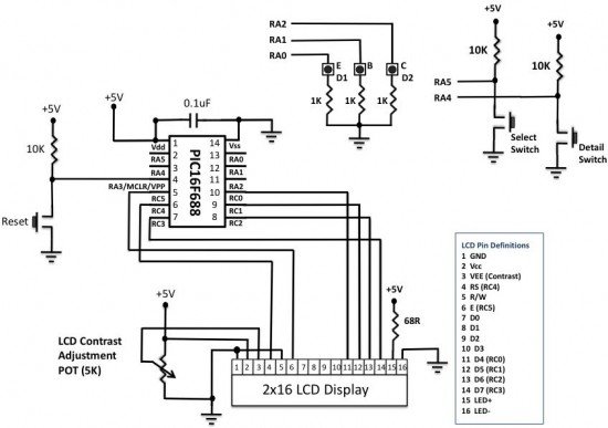
Circuit Diagram and Description
The circuit diagram for this project is pretty simple. It has two push button switches for inputs, named Select and Detail. Pressing the Select button allows to choose between the diode and transistor testings, and the Detail button is active only in case of transistor testing and displays the details of the test results like the transistor type and both the junction status. The three legs of a test transistor (E, B, and C) are grounded through 1 K resistors, and the two PN junctions will be tested through RA0, RA1, and RA2 port pins of a PIC16F688 microcontroller. The testing of a diode requires only two pins, and will use the E and C pins. That’s why they have alternate labels, D1 and D2, in the circuit diagram.
For more detail: Microcontroller based Diode and Bipolar Junction Transistor (BJT) tester
- What is the main purpose of this project?
The purpose is to demonstrate a simple way to construct a testing device for diodes and bipolar junction transistors using a microcontroller. - How does the logic behind testing a diode work?
A good diode conducts current in only one direction; if it conducts in both directions it is short, and if neither, it is open. - Which microcontroller is used in this project?
A PIC16F688 microcontroller is used to switch bias voltage and determine junction status. - How many I/O pins are required to implement the testing algorithm for a transistor?
Three I/O pins of a microcontroller are required to implement the testing algorithm for a transistor. - What happens if both BE and BC junctions conduct in only one direction?
If only the BE and BC junctions conduct, the transistor is of NPN type and is working fine. - What indicates a transistor is not good?
Cases like EB and BE both conducting, or BC and CB both not conducting, indicate the transistor is not good. - What is the function of the Select button?
Pressing the Select button allows the user to choose between diode and transistor testing. - When is the Detail button active?
The Detail button is active only in case of transistor testing to display details like transistor type and junction status.