Summary of Digital Clock Using Microcontroller 89C52/89S52
This simple mini project teaches how to build a digital clock using an 89C52 (or 89S52) microcontroller, interfaced with a 16x2 LCD and selectable 12/24-hour modes via input pins. It uses Proteus for simulation and Keil for compiling; port 1 is input (mode selection), port 2 is output to peripherals. The article outlines required components and gives an example C code snippet initializing time variables and checking mode pins.
Parts used in the Digital Clock Using Microcontroller 89C52 89S52:
- Microcontroller 89C52 (89S52 also acceptable)
- Ceramic capacitors 22pF (2 pieces)
- Reset switch (button)
- Electrolytic capacitor 10uF, 25V
- Crystal oscillator 11.0592MHz
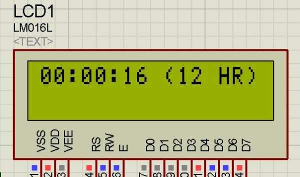
- 16x2 LCD display
- Resistor 10k
Are you a beginner in micro controller projects?and are you stuck where to start from?if yes,then this is one of the simplest mini projects that you can start from . This mini project will give you a clear understanding of programming your micro controller. we sometimes look at our watch and wonder ” how does this thing work”. Well, in this digital clock project, you will gain some insight on how micro controller can be used to make it work as a Digital Clock.
 Components required:
- 1 microcontroller 89C52(89S52 will also do)
- 2 ceramic capacitors-22pF
- 1 switch(button for reset purpose)
- 1 electrolytic capacitor-10uF,25V
- 1 crystal oscillator-11.0592MHz
- 16×2 LCD display
- 1 resistor-10k
Software you will need
This project has been done in proteus software.If you are new to proteus software, the tutorials given below may get you started with the software.note:if you are familiar with proteus you can skip this part.
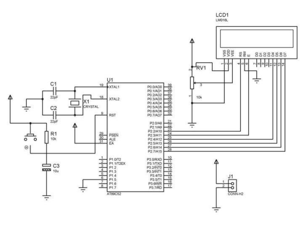
The programming of the microcontroller is done using keil compiler.port 2 of 89C52 is used as the output port.whereas port 1 is used as the input port.when P1_4 is grounded the 12 hr mode is activated and when P1_5 is grounded the 24 hr mode is activated.
The detail explanation of the code is done below:
#include “REGX52.H”
#include “delay.h”
#include “lcd.h”
void main(void)
{int hr=0; /*initiate hour=0 */
int min=0; /*initiate minutes=0 */
int sec=0; /*initiate seconds=0 */
P1=0xff; /*set port 1 as input port */
P2=0x00; /*set port 2 as output port*/
while(1)
{ LCD_INIT(); /*initialize LCD*/
if (P1_4==0)/*if P1_4 is grounded enter the 12hr loop */{
For more detail: Digital Clock Using Microcontroller 89C52 89S52
- What microcontroller is used in this digital clock project?
The project uses the 89C52 microcontroller and states 89S52 will also do. - Which pins select 12 hr and 24 hr modes?
P1_4 grounded activates 12 hr mode and P1_5 grounded activates 24 hr mode. - Which port is used as the input port?
Port 1 of the 89C52 is used as the input port. - Which port is used as the output port?
Port 2 of the 89C52 is used as the output port. - What display is used for showing time?
A 16x2 LCD display is used in the project. - What software is used to simulate the project?
The project has been done in Proteus software. - What compiler is used to program the microcontroller?
The Keil compiler is used for programming in this project. - What crystal frequency is required?
The project uses an 11.0592MHz crystal oscillator.